
Wearable communication device

a communication device and wearable technology, applied in the field of wearable communication devices, can solve the problems of not responding to a call, user cannot use the phone immediately, and sometimes the voice of the recipient is difficult to hear

Inactive Publication Date: 2005-06-28
NIPPON TELEGRAPH & TELEPHONE CORP
View PDF13 Cites 108 Cited by
  • Summary
  • Abstract
  • Description
  • Claims
  • Application Information

AI Technical Summary

Benefits of technology

[0012]Accordingly, it is a general object of the present invention to provide a wearable communication device which can be used without annoying surrounding people and without being influenced by an outside noise.
[0013]It is another object of the present invention to provide a wearable communication device and a wearable PDA device which improve operability and usability.

Problems solved by technology

However, because a user needs to take the phone out from a pocket or a bag when the user needs to use it, there are disadvantages that the user can not use the phone immediately when he wants to do so and can not respond to a call immediately.
However, because a microphone and a speaker of the telephone are located at the wrist, there are disadvantages that, for example, a received voice is sometimes hard-to-hear and a user's utterance sometimes is not transmitted to the party on the other end.
Further, as for a conventional mobile telephone such as a conventional cellular phone, the user's utterance tends to be loud when using the telephone, and the other party's speaking voice leaks from the receiver.
Further, the alert of the phone is very loud.
Therefore, a disadvantage that such a telephone sometimes annoys surrounding people is pointed out.
As for other types of wearable telephones such as the above-mentioned wristwatch type and a conventional ear-attaching type, because the using styles of those types are different from the style when using a conventional handset, there is a problem that the style seems to be strange and may be problematic.
Also, as those telephones become small, the operating buttons become quite small.
As a result, the user can not operate those telephones easily.
However, as mentioned above, because the user's utterance tends to be loud when using the phone and the other party's speaking voice leaks from the receiver, there is also the disadvantage of annoying surrounding people in a crowded place.
Also, the difficulty of the operation due to the small size is still a problem.
Furthermore, in a recent situation in which a small PDA device is becoming widely used, the above-mentioned operability problem needs to be solved so that the PDA may become even smaller so as to be wearable on an arm or a hand.

Method used


Image

  • Wearable communication device
  • Wearable communication device
  • Wearable communication device

Examples


first embodiment

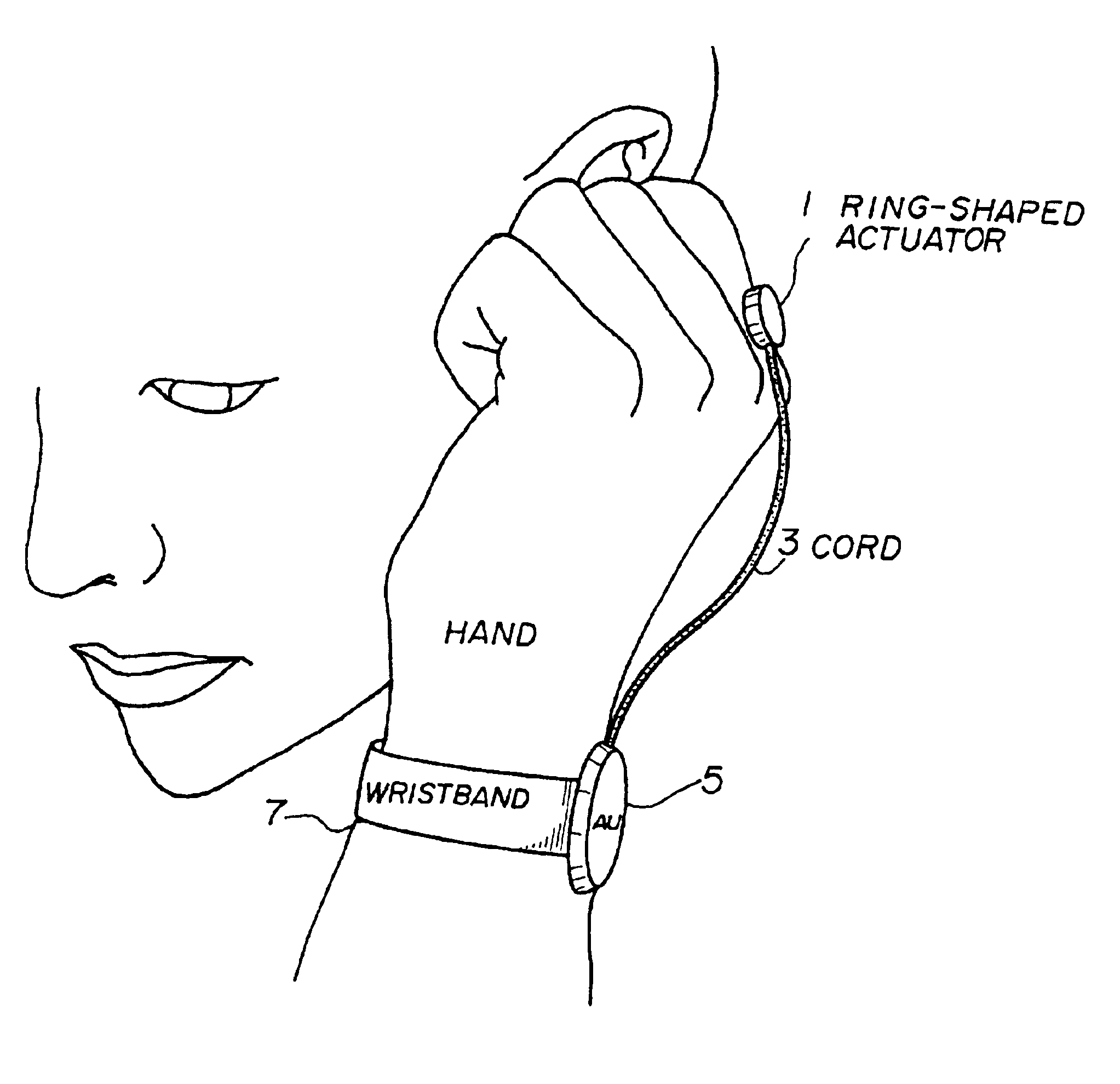
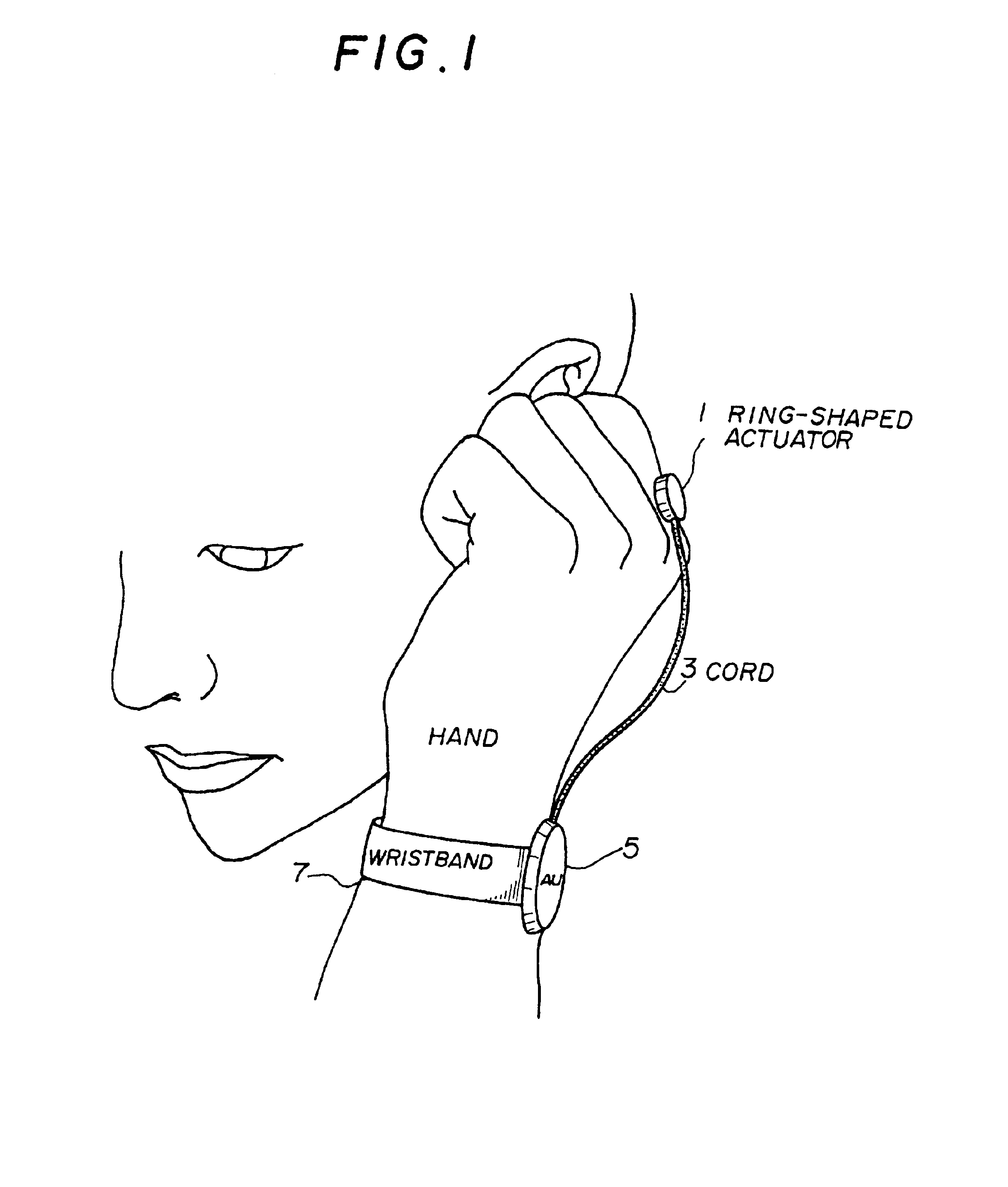
[0151]FIG. 1 is a schematic perspective diagram showing a wearable receiver of the present invention.

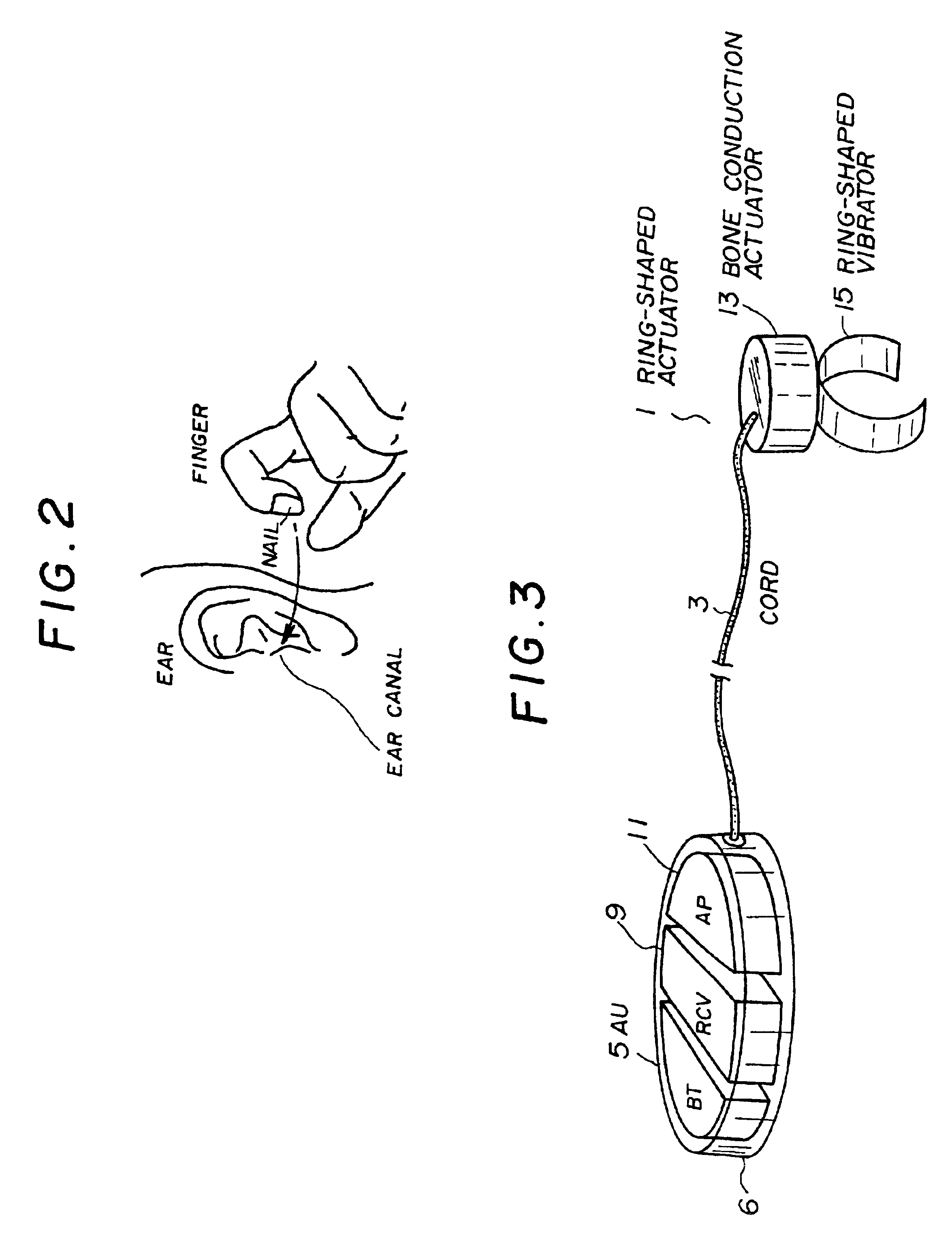
[0152]As shown in FIG. 1, the wearable receiver includes a ring-shaped actuator 1, a cord 3, an amp unit (AU) 5 and a wristband 7. The ring-shaped actuator 1 which has a ring-shaped vibrator and a bone conduction actuator is mounted on a base of the user's finger, and the amp unit (AU) 5 is mounted on the user's wrist with the wristband 7. When the user use the wearable receiver, as shown in FIG. 2, the user covers the ear canal with a fingernail or inserts a finger into the ear canal or touches the user's finger to a part near the user's ear.

[0153]FIG. 3 is a perspective view showing the inside of the wearable receiver in detail. As shown in the figure, the amp unit (AU) 5 includes a battery (BT) 6 for supplying power, a wireless receiver (RCV) 9 and an amp (AP) 11 for driving the bone conduction actuator. Hereinafter, the amp (AP) for driving the bone conduction actuator will be re...

second embodiment

[0158]FIG. 6 shows a wearable receiver of the present invention. As shown in FIG. 6, a connector 25 which is detachable from an actuator 23 is provided on the upper side of the actuator 23. A cord 27 connecting between an amp unit 29 and the actuator 23 can be stored in the amp unit (AU) 29.

[0159]FIG. 7 shows a sectional view of the connector (CN) 25 and the amp unit (AU) 29. FIG. 8 is a perspective diagram of the wearable receiver. As shown in FIG. 7, the amp unit 29 stores the cord 27 by wrapping it around the center part of the amp unit. Also, the connector 25 acts as a switch. To be more specific, a base (SWB) 31 of the connector can be inserted into an outlet (SWA) 33 of the case, and the switch is operated by connecting the SWA33 and the SWB31. The SWA33 forms a pair of electrodes, and the switch is realized by allowing the SWB31 to contact the pair of electrodes. The switch can be realized in various ways. For example, the SWA33 can be made of a Hall device and the SWB31 can ...

fourth embodiment

[0165]FIG. 13 is a schematic perspective diagram showing a wearable receiver of a As shown in (a) of the figure, the wearable receiver includes an amp unit (AU) 38 and a boom (BM) 40 which extends from the amp unit (AU) 38. An actuator (AC) 42 is provided at an end point of the boom (BM) 40. As shown in (b) of the figure, the part which contacts the back of the hand is shaped like a smooth dome which is downward convex, and the surface of which part is processed with teflon and the like so as to reduce friction. The amp unit (AU) 38 is mounted on the wrist by the wristband 44. Also, the wearable receiver has an ON / OFF switching mechanism using expansion and contraction of the boom (BM) 40. The boom (BM) 40 can be stored into the amp unit (AU) 38. FIG. 14 shows a case in which the boom is stored.

[0166]As shown in FIG. 13, when the user uses this wearable receiver, the user bends the hand backwards and brings the end of the boom into contact with the back of the hand, specifically, w...


PUM


Abstract

A wearable communication device includes a bone conduction actuator which is applicable for being in contact with a user's wrist, hand, back of the hand, finger or nail in order to transmit voice signals. The user inserts the user's finger into the user's ear canal, or touches the user's finger to a part near the user's ear, or puts the user's fingertip or nail on the user's ear canal so as to block the user's ear canal when the user uses the wearable communication device. Also, the wearable command input device includes a first part for detecting shock or acceleration which arises when the user taps the user's fingertip on the surface of an object or when the user taps the fingertips mutually and which is transmitted through the user's finger, a second part for detecting specific frequency components which are included in signals from the first part and for detecting the presence or the absence of the tap of the finger of the user, and a part for determining and executing commands based on series of signals output from the second part.

Description

BACKGROUND OF THE INVENTION[0001]1. Field of the Invention[0002]The present invention generally relates to a wearable communication device such as a wearable telephone. Further, the present invention relates to a wearable communication device which can be used in a noisy outdoor environment and can be used without annoying surrounding people.[0003]Furthermore, the present invention relates to a wearable command input device, more particularly, to a full-time wearable command input device in which a user can input a command by minute movements of a human body while preventing any improper input caused by bending or twisting the user's wrist from being input as a command.[0004]2. Description of the Related Art[0005]A conventional mobile telephone such as a cellular phone is generally used by being grasped with a hand. However, because a user needs to take the phone out from a pocket or a bag when the user needs to use it, there are disadvantages that the user can not use the phone imm...

Claims


Application Information

Patent Timeline
IPC IPC(8): G09B21/00G06F3/00G06F3/023G06F1/16G06F3/01
CPCG06F1/163G09B21/00G06F3/014H04R2460/13
Inventor FUKUMOTO, MASAAKITONOMURA, YOSHINOBU
Owner NIPPON TELEGRAPH & TELEPHONE CORP
Learn More