Mechanically actuated evanescent-wave coupled optical devices

a coupled optical device and evanescent wave technology, applied in the field of mechanically actuated evanescent wave coupled optical devices, can solve the problems of inconvenient coupling of optical waves to electromagnetic signals, less reliable manufacturing, and relatively difficult manufacturing, and achieve the effects of relatively reliable and robust manufacturing, substantially altered propagation parameters of waveguides

Inactive Publication Date: 2005-06-21
CLAREO PHOTONICS
View PDF23 Cites 46 Cited by
  • Summary
  • Abstract
  • Description
  • Claims
  • Application Information

AI Technical Summary

Benefits of technology

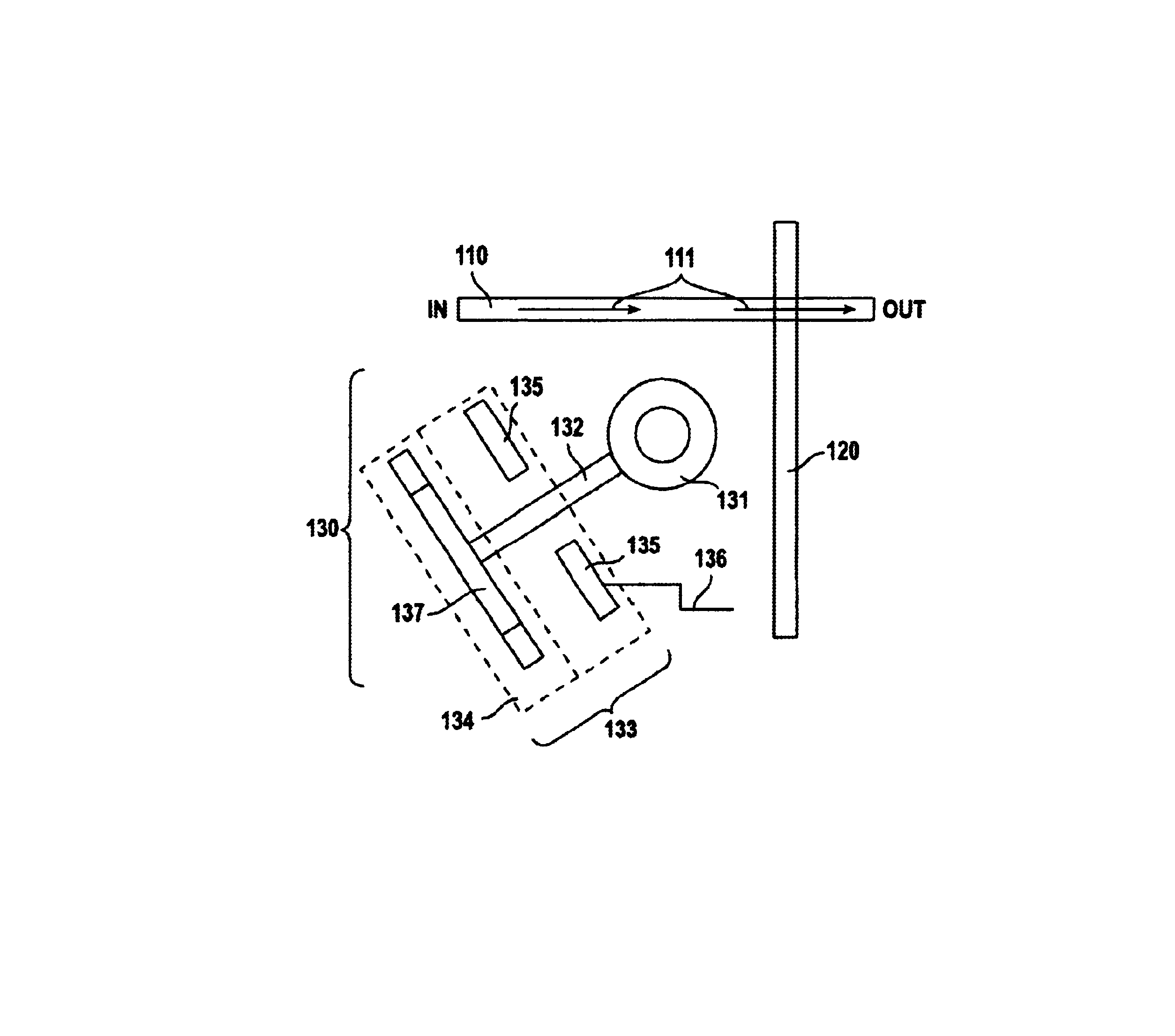
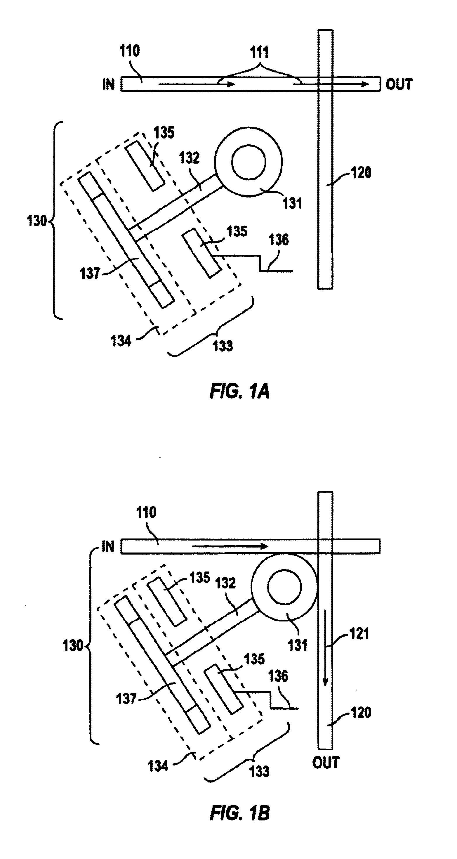
[0007]The invention includes apparatus, and methods for making and using the same, which operate using mechanically-actuated evanescent wave coupling. In one embodiment, at least a portion of an optical waveguide is integrated onto a substrate, and an optical device or element (such as an resonator, for example one shaped in the form of a disk or a ring, or such as a second optical waveguide) are physically moved relatively to each other, with the result that propagation parameters for the waveguide are substantially altered. Altered propagation parameters (such as phase delay or coupling with another waveguide) within the waveguide can be used to cause an optical wave propagated by the waveguide to be sensed, switched, modulated, or otherwise transformed, in response to a control or data signal; the control or data signal might be electromagnetic, optical, sonic, or another type of signal. Active elements such as amplifiers, laser, or photodiodes, can also be coupled to the system. Physical parts of the apparatus can vary widely in both size and tolerance, with a result that manufacturing is relatively reliable and robust.

Problems solved by technology

However, optical waves are not conveniently coupled to electromagnetic signals (whether control signals or data signals), particularly when those optical waves are being propagated using elements integrated onto a substrate.
However, this method is subject to the drawback that it uses relatively high-precision (for patterning, placement, and fabrication) with respect to the position of the optical waveguides and the electromagnetic elements, with a result that manufacturing is relatively more difficult and less reliable.

Method used


Image

  • Mechanically actuated evanescent-wave coupled optical devices
  • Mechanically actuated evanescent-wave coupled optical devices
  • Mechanically actuated evanescent-wave coupled optical devices

Examples


Embodiment Construction

[0017]In the description herein, a preferred embodiment of the invention is described, including preferred process steps, materials and structures. Those skilled in the art would realize, after perusal of this application, that embodiments of the invention might be implemented using a variety of other techniques not specifically described, without undue experimentation or further invention, and that such other techniques would be within the scope and spirit of the invention.

Lexicography

[0018]The following terms relate or refer to aspects of the invention or its embodiments. The general meaning of each of these terms is intended to be illustrative and in no way limiting.[0019]disk or ring—In general, these refer to any shape substantially having a disk or ring shape, but is not restricted in any way to a symmetrical or a smooth shape. For example, a disk or ring might include a polygon (such as a hexagon, pentagon, or square), or might include an asymmetric shape (such as an ellipse ...


PUM


Abstract

Apparatus using mechanically-actuated evanascent wave coupling. At least a portion of an optical waveguide is integrated onto a substrate, and an optically active element is physically moved relatively to each other, with the result that propagation parameters for the waveguide are substantially altered. The optically active element may be a resonator or another waveguide. Altered propagation parameters can be used to cause an optical wave to be transformed in response to an electromagnetic signal. Physical parts of the apparatus can vary widely in both size and tolerance. The optically active element is mechanically actuated relative to a position of the optical waveguide.

Description

[0001]This application is a continuation in part of U.S. Ser. No. 10 / 091,604, filed on 5, Mar. 2002, abandoned 12 June 2002.BACKGROUND OF THE INVENTION[0002]1. Field of the Invention[0003]The invention relates to mechanically actuated evanescent-wave coupled optical devices.[0004]2. Related Art[0005]When propagating optical waves (such as through an optical waveguide integrated onto a substrate), it is desirable to be able to switch, modulate, or otherwise transform, those optical waves in response to a signal, such as can easily be done when propagating electromagnetic signals. However, optical waves are not conveniently coupled to electromagnetic signals (whether control signals or data signals), particularly when those optical waves are being propagated using elements integrated onto a substrate.[0006]One method shown in U.S. Pat. No. 6,009,115 attempts (see U.S. Patent and references therein) to switch optical waves in response to electromagnetic control signals using an electro...

Claims


Application Information

Patent Timeline
Patent Type & Authority Patents(United States)
IPC IPC(8): G02B6/12G02B6/34G02B6/35
CPCG02B6/12007G02B6/3536G02B6/29343G02B6/29352G02B6/3508G02B6/3594G02B6/3546G02B6/3548G02B6/357
Inventor MESSICA, AVIMESSICA, ASNAT
Owner CLAREO PHOTONICS
Why Eureka
Try Eureka