
Rack mountable computer component and method of making same

a computer and component technology, applied in the direction of electrical equipment construction details, furniture parts, instruments, etc., can solve the problems of wasting space in the back plane and fan exhaust plenum, time-consuming replacement, and high cost of individual fans mounted in each componen

Active Publication Date: 2005-06-21
BOXX TECH LLC +1
View PDF54 Cites 82 Cited by
  • Summary
  • Abstract
  • Description
  • Claims
  • Application Information

AI Technical Summary

Benefits of technology

"The present invention is a rack mounted system that includes a rack housing with a plurality of vertical bays for accommodating computer components. The system also includes a control bay for supplying power to various components. The rack housing has a bottom opening for air flow and a fan / LAN tray for facilitating air flow through the components. The system also includes casters for easy portability and a locking mechanism for securely mounting the system. The technical effects of the invention include a compact and closely spaced configuration for computer components, improved air flow through the components, and easy portability of the system."

Problems solved by technology

The individual fans mounted in each component are expensive, and time-consuming to replace in case of malfunctions.
Also, the back plane space and fan exhaust plenum chamber are wasted space in that they occupy spaces which could otherwise be filled with computer components.
Such an operation is time consuming, and therefore expensive since highly trained personnel are required to do such an installation.
This, too, is time consuming and expensive.
Such a configuration of the circuit boards within the computer component housing is less than desirable for some applications.
It is difficult to accomplish ordinarily because the access to the mother board is disposed at the rear of the housing.
In this regard, access to a given computer component must be made at the rear of the rack where a large number of cables are present and thus block access to the computer module.
Additionally, by mounting the mother board at the rear of the component housing, it is frequently difficult and expensive to mount fans and baffles to direct air entering the front of the housing and being exhausted from the rear thereof.

Method used


Image

  • Rack mountable computer component and method of making same
  • Rack mountable computer component and method of making same
  • Rack mountable computer component and method of making same

Examples


Embodiment Construction

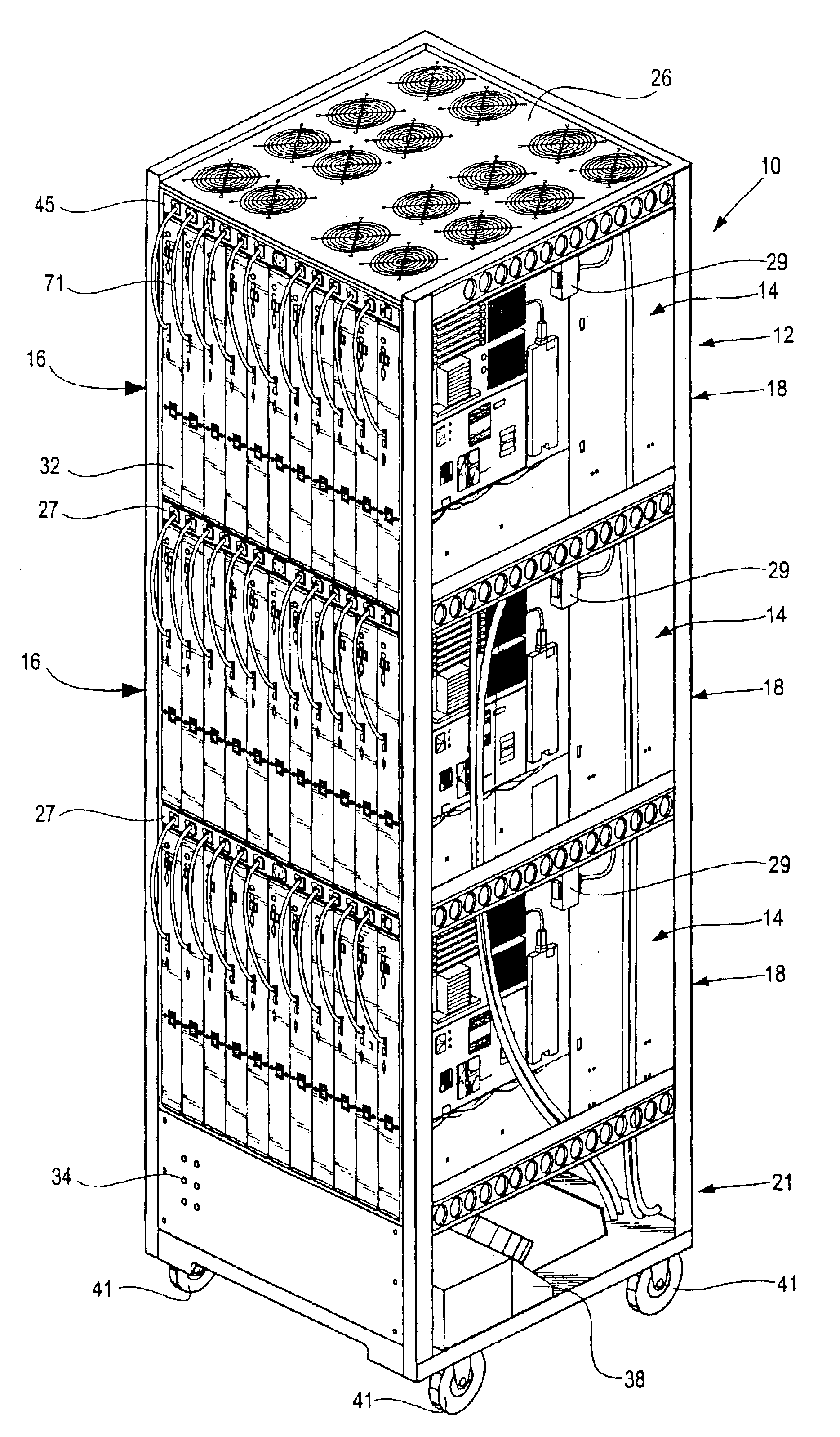
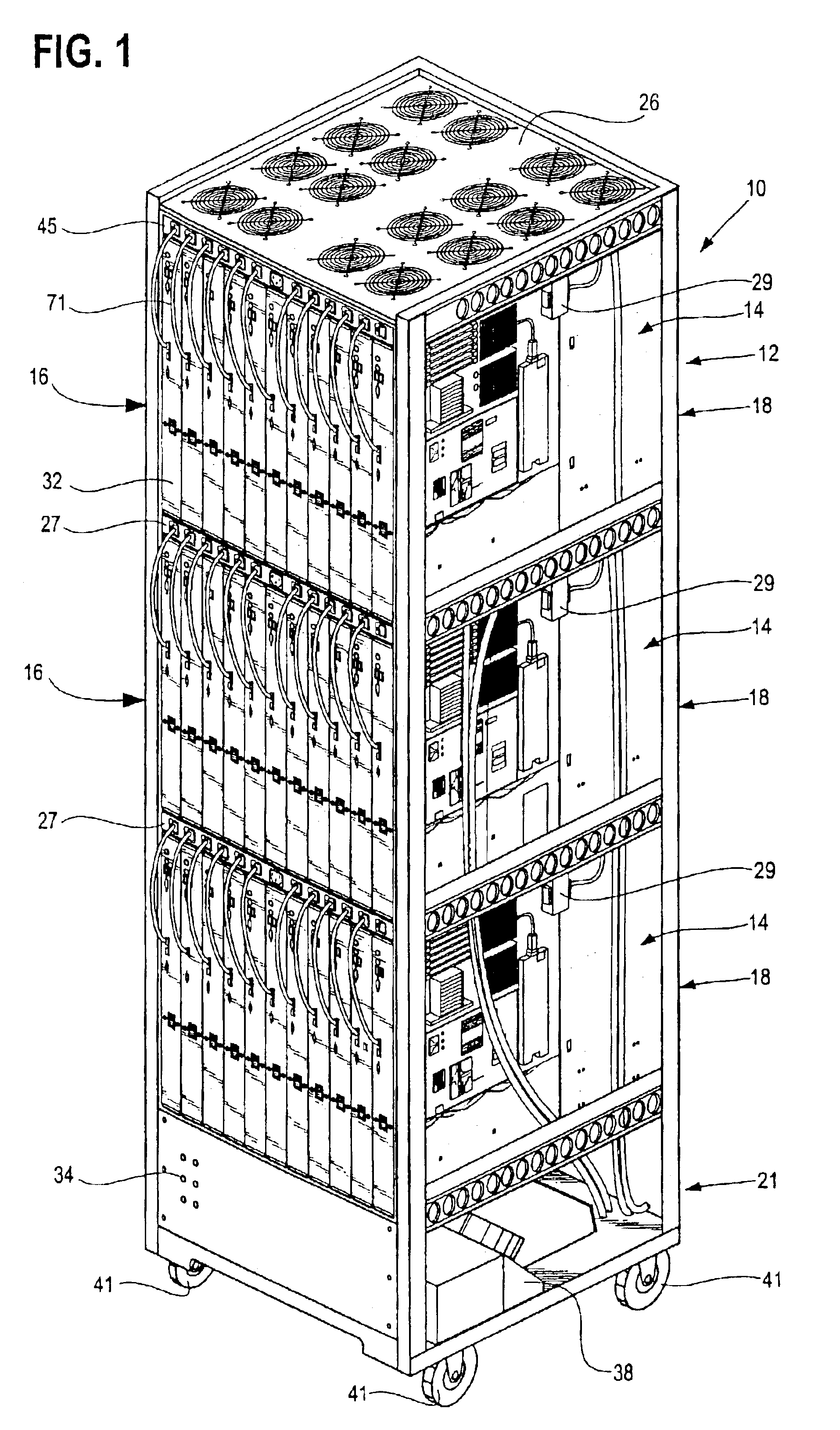
[0045]According to at least one of the disclosed embodiments of the present invention, there is disclosed a rack mountable computer component which is in the form of an open computer component or blade construction which is adapted to be mounted in a generally upright or vertical disposition within a rack. The operative components such as mother boards are mounted at the front of the component or blade to permit access by the user thereto. The operative components are cooled by vertical air flow relative to the mounted blade to facilitate cooling thereof.

[0046]According to disclosed embodiments of the invention, the component construction includes a support having the active components mounted on at least one side thereof and being adapted to be supported in a generally upright configuration. A front panel extends transversely to a front edge portion of the support and an outlet disposed thereat is connected to at least one of the operative components. An electrical power inlet is m...


PUM


Abstract

According to at least one of the disclosed embodiments of the present invention, there is disclosed a rack mountable computer component which is in the form of an open computer component or blade construction which is adapted to be mounted in a generally upright or vertical disposition within a rack. The operative components such as mother boards are mounted at the front of the component or blade to permit access by the user thereto. The operative components are cooled by vertical air flow relative to the mounted blade to facilitate cooling thereof.

Description

RELATED APPLICATION[0001]This application claims priority to the following U.S. provisional applications: Ser. No. 60 / 384,996, titled “Rack Mountable Computer Component and Method of Making Same”, filed May 31, 2002 now abandoned; Ser. No. 60 / 384,987, titled “Rack Mountable Computer Component Cooling Method and Device”, filed May 31, 2002 now abandoned; Ser. No. 60 / 384,986 filed on May 31, 2002, now abandoned titled “Rack Mountable Computer Component Fan Cooling Arrangement and Method”, and Ser. No. 60 / 385,005 filed on May 31, 2002, now adandoned, titled “Rack Mountable Computer Component Power Distribution Unit and Method”, which are each hereby incorporated by reference in their entirety.[0002]This application relates to the following U.S. non-provisional patent applications: Ser. No. 10 / 448,691, titled “Rack Mountable Computer Component Cooling Method and Device,” filed May 28, 2003; Ser. No. 10 / 290,676 titled “Rack Mountable Computer Fan Cooling Arrangement Method;” and Ser. No....

Claims


Application Information

Patent Timeline
Patent Type & Authority Patents(United States)
IPC IPC(8): G06F1/20G06F1/18H05K7/14
CPCG06F1/181G06F1/183H05K7/1488H05K7/1487G06F1/20
Inventor SMITH, JOHN V.HESTER, VICTOR P.WYLIE, WILLIAM A.
Owner BOXX TECH LLC
Learn More