
Roll cage

a technology of roller cages and body covers, applied in the direction of toys, vehicle components, pedestrian/occupant safety arrangements, etc., can solve the problems of body covers being damaged, plastic body covers being subject to considerable stress, and sometimes rolling

Inactive Publication Date: 2005-06-21
SCARLA ROBERT
View PDF11 Cites 20 Cited by
  • Summary
  • Abstract
  • Description
  • Claims
  • Application Information

AI Technical Summary

Benefits of technology

[0009]It is a further object of this invention to provide an improved flat stock metal roll cage for supporting the body and protecting the operating components of a model car or truck.

Problems solved by technology

When the models are raced against one another, or when they are operated over rough terrain, they occasionally roll over.
When this occurs, the plastic body cover undergoes considerable stress, and often the body cover is damaged.
In addition, the common mounting of the body cover to the shock absorber towers may result in breaking of the towers in a rollover, since typically they also are made of plastic.
If the body cover, which is a relatively weak, lightweight component, is crushed or broken away, the operating components of the model attached to the underlying chassis also may be subjected to damage by contact with the ground in the event of a rollover.
The vehicle, however, is not a radio controlled model car or truck; and the roll bar simply serves as a connecting member for attaching clips on the underside of the top to securely hold the top on the body.

Method used


Image

  • Roll cage
  • Roll cage
  • Roll cage

Examples


Embodiment Construction

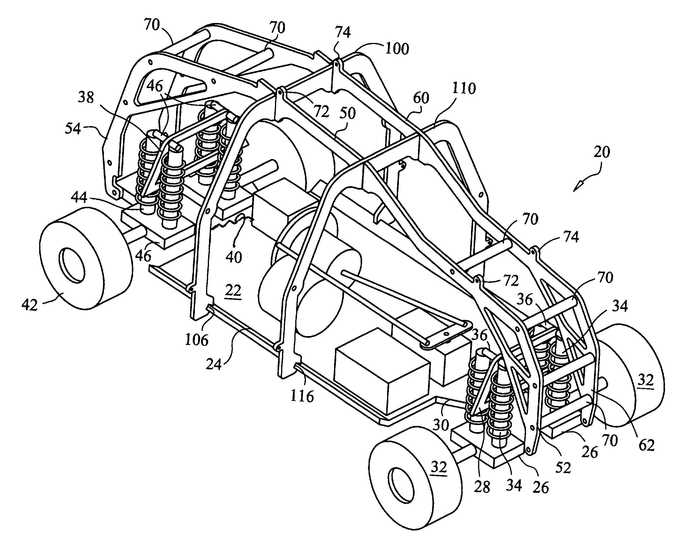
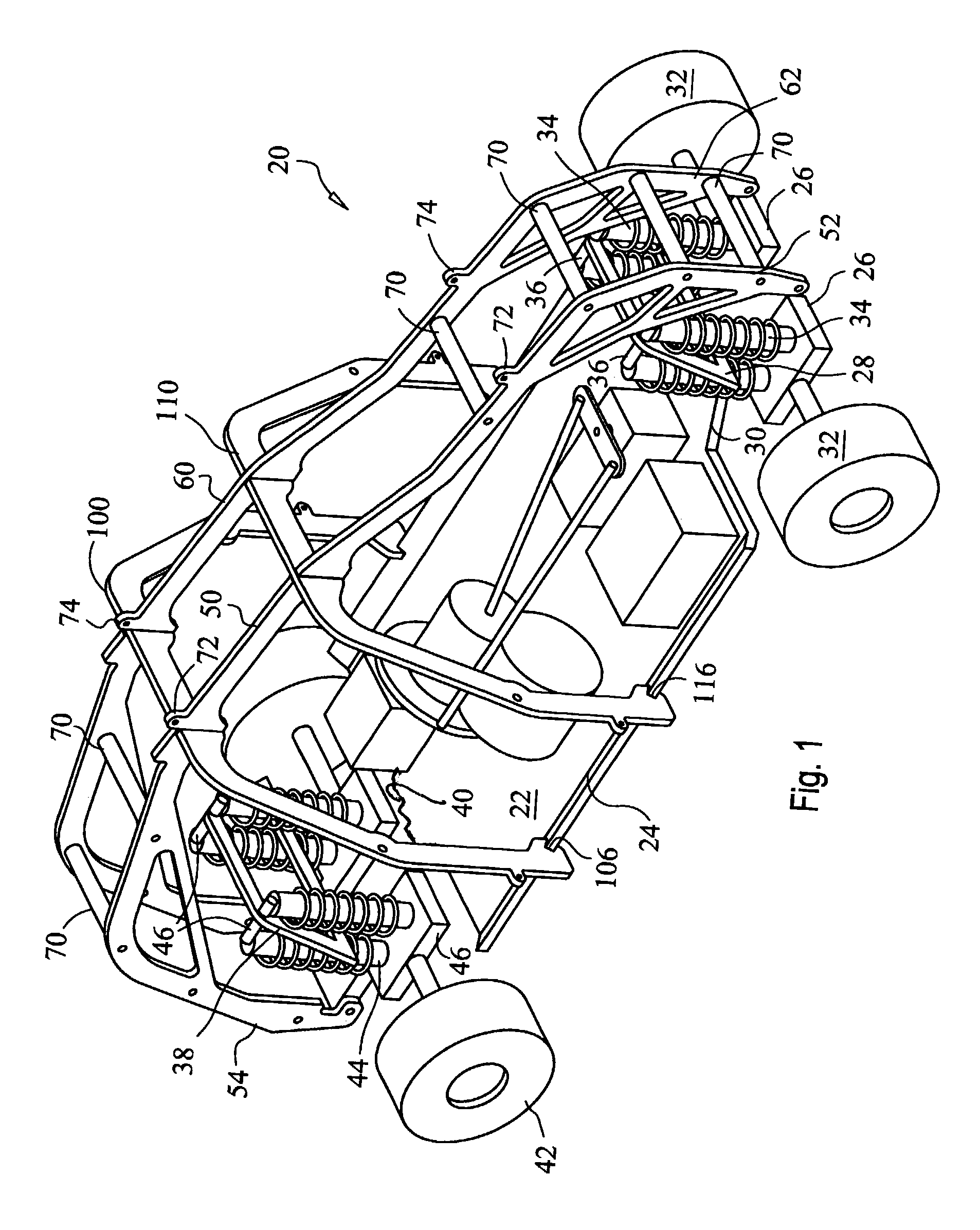
[0016]Reference now should be made to the drawing, in which the same reference numbers are used throughout the different figures to designate the same or similar components. FIG. 1 is a top perspective view of a model car or truck chassis to which a preferred embodiment of the invention has been mounted or attached. The model car 20 of FIG. 1 is diagrammatically illustrated; and the actual detailed physical interconnections of various parts of the model car which are not necessary for an understanding of the present invention are show only in diagrammatic form.

[0017]Basically, the model car 20 which is shown in FIG. 1 is a radio-controlled (RC) gasoline or electric powered model car of a generally conventional design. The car 20 includes a chassis plate 22, which either may be an original equipment chassis plate or one which is provided as a modification to the original model car kit.

[0018]As illustrated in FIG. 1, the chassis plate 22 has slightly upturned longitudinal edges 24 on ...


PUM


Abstract

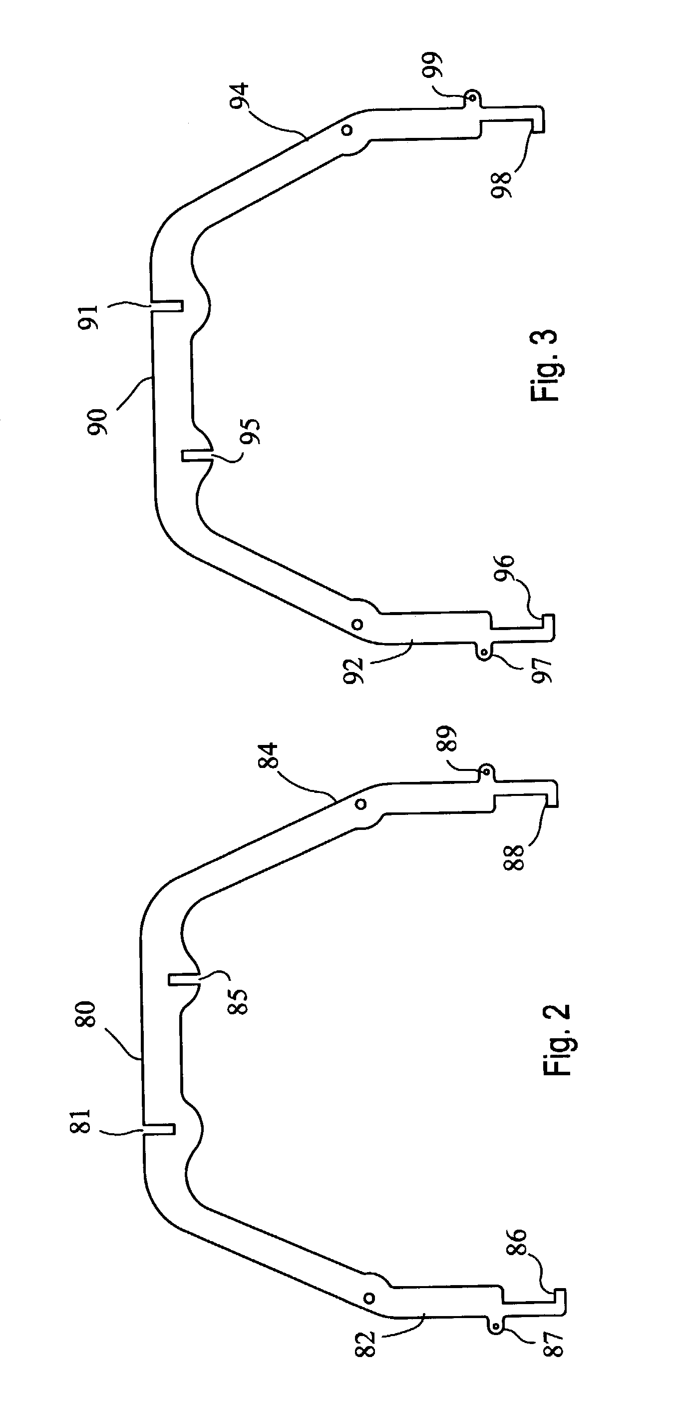
A roll cage for a model car or truck is made of first and second elongated members and first and second inverted U-shaped cross members fabricated from flat metal stock. The roll cage is assembled by slip-fitting it together at mating slots formed into the elongated roll cage members and the inverted U-shaped roll cage members. A rigid roll cage is formed, which then is attached to the chassis of the model car or truck to overlie the components mounted on that chassis.

Description

BACKGROUND[0001]Substantial interest has developed in the operation and competitive racing of radio controlled, gasoline and electric powered model automobiles and trucks of relatively sophisticated design. These model trucks and automobiles use small, high performance gasoline and engines and include transmissions, radio controlled power steering mechanisms and sophisticated suspension systems. The models typically are between two and three feet in length, with proportionate width, and generally have a plastic “body” cover mounted over the operating components on the chassis of the model. Typically, the plastic body, which provides the overall esthetic appearance, of the model is mounted at the front and rear onto shock absorber towers for the front and rear wheels.[0002]Gasoline and electric powered radio controlled model automobiles and trucks of the general type described above are capable of being operated at relatively high speeds, on the order of 40 MPH, or more. In addition,...

Claims


Application Information

Patent Timeline
Patent Type & Authority Patents(United States)
IPC IPC(8): A63H17/00A63H17/26
CPCA63H17/262
Inventor SCARLA, ROBERT
Owner SCARLA ROBERT
Learn More