
Computer input device with individually positionable and programmable input members

a computer input and input member technology, applied in the field of computer input devices, can solve the problems of inability to keep up with the development of other aspects of computer technology, the location, quantity, and function of individual tactile mechanisms, and the inability to operate sliders with mouse-controlled cursors on computer screens, etc., to achieve the effect of facilitating accurate user input to applications

Inactive Publication Date: 2005-06-07
ERGODEX
View PDF39 Cites 176 Cited by
  • Summary
  • Abstract
  • Description
  • Claims
  • Application Information

AI Technical Summary

Benefits of technology

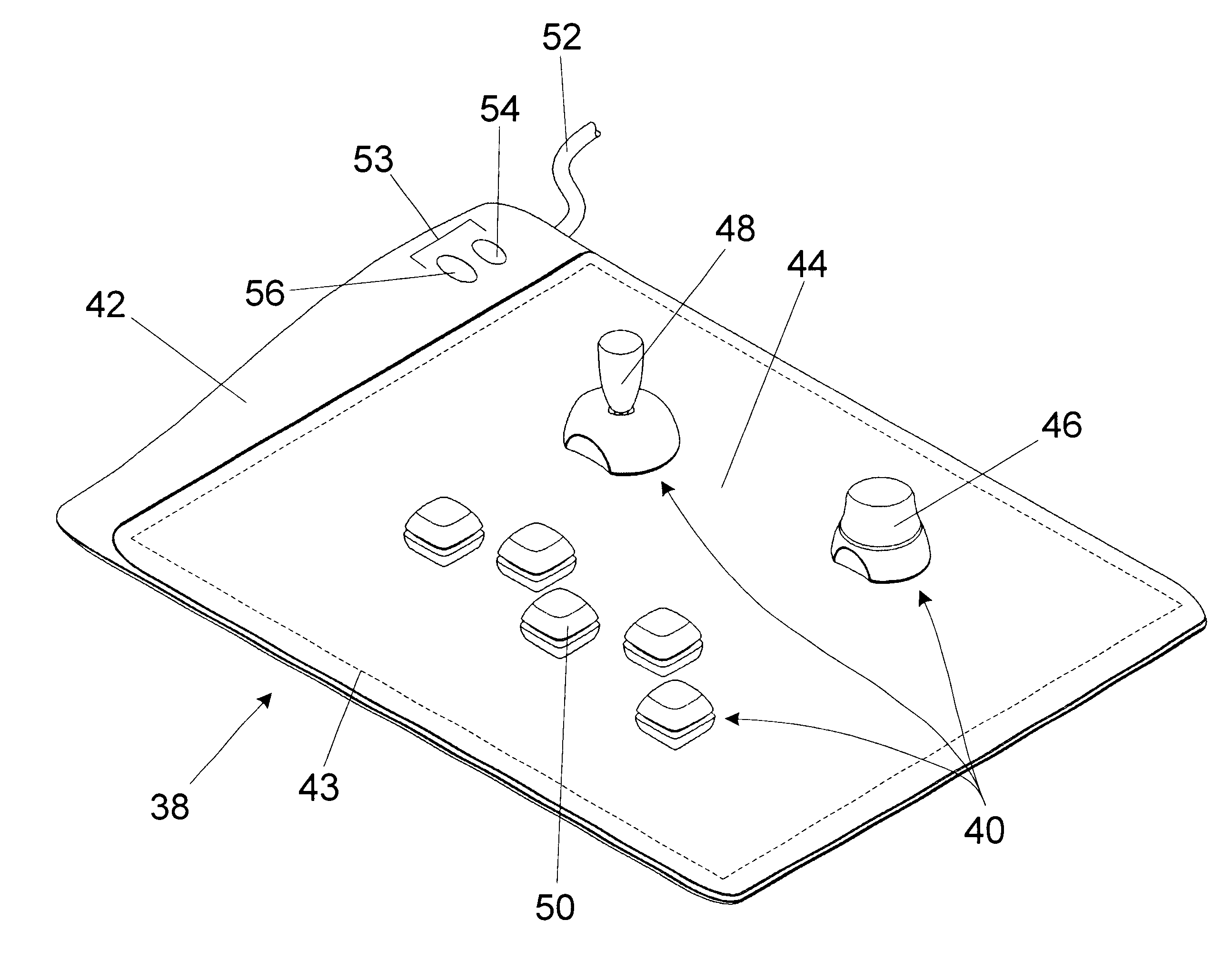
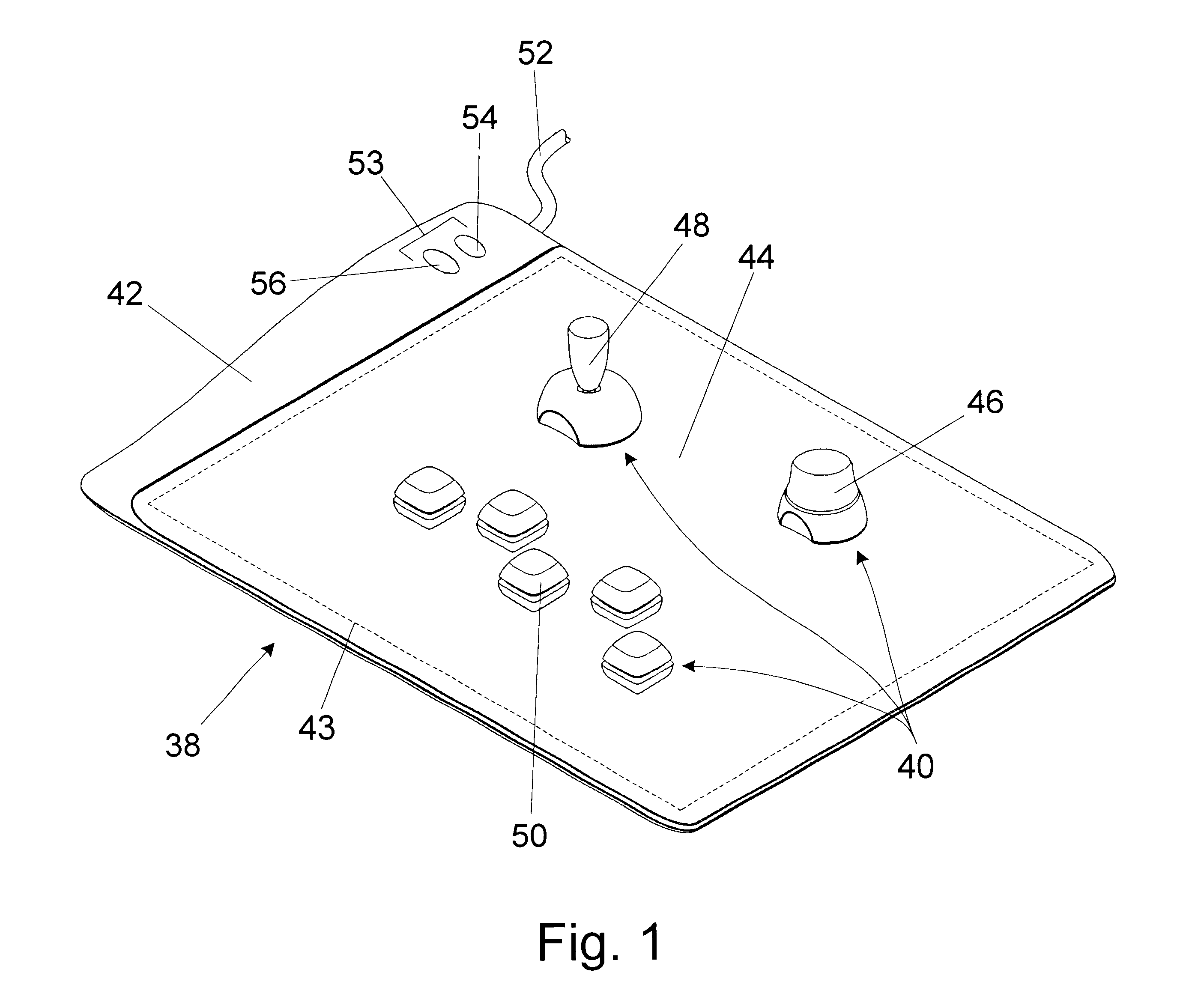
[0006]The present invention provides a revolutionary new input device. Among the advantages of the present invention are that it can include a number of input members or mechanisms. Along these lines, the present invention can include keys, buttons, button pads, key pads, thumb pads, joysticks, sliders, dials, trackpads, jog / shuttle wheels, and / or any other input member. The input members may be analog or digital. As a result, the present invention can replace cumbersome actuation of screen-based input with tactile user operated input members and, as a result, greatly facilitate accurate user input to applications.
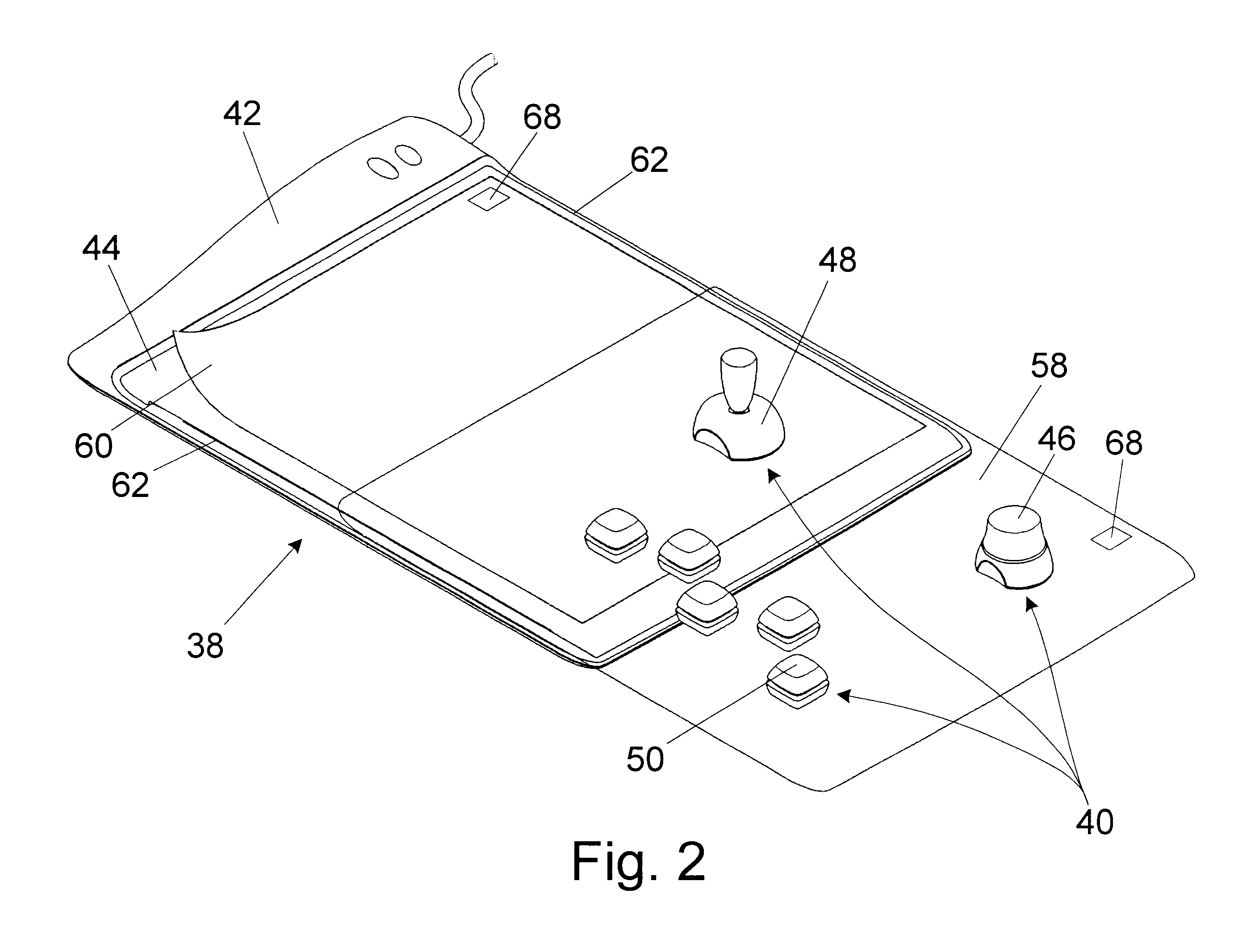
[0007]Additionally, the present invention provides a computer input device that permits users to individually locate in desired positions a plurality of input members or mechanisms. Each input member may be individually programmed with one or more input functions. Among the advantages of the present invention is that any desired input members may be included in the device. The present invention permits a user to select an optimum mix, based upon type, number, position, orientation or any other parameter, of input members to use for specific tasks. Therefore, the present invention permits a user to create a custom input device with respect to the input members included and their arrangement.
[0008]When arranging the input members, a user may select, among other things, the position and orientation of each individual input member relative to the other input members as well as within the custom input device as a whole. For example, users can arrange the input members to conform to their unique hand geometry, increasing the comfort of using the input device. Alternately, users may arrange the input members into logical groupings according to function.
[0009]Significantly, as users, applications, user needs and / or other parameters change, the present invention can provide the ability to alter the positions of the input members. Also, input members may be added and / or subtracted from the input device. This further enhances the adaptability of the input device of the present invention.
[0011]Thus, the present invention can provide the ability to create an input device customized on a variety of levels. As such, the present invention provides a new computer input device with a functionality that is orders of magnitude beyond existing input devices.
[0012]As described herein, the present invention allows each user to specify the number, type, location, and function of each input mechanism, thereby offering the ability to create a personalized computer input device. The personalized interface may allow the user to place all the controls they need, but only the controls they use, and to place them in an arrangement that is logical, comfortable, and efficient for them. Furthermore, the present invention allows the user, at any time, to reconfigure the input device to add or remove features, as well as to adjust the device for other, very different, types of computer input functions, such as word processing or computer aided design (CAD). A graphical interface allows the input device to be configured to work the same across multiple software applications, or to perform a different task within each application.

Problems solved by technology

Advancements in computer input device technology have failed to keep up the pace with development in other aspects of computer technology.
Operating a slider with a mouse-controlled cursor on a computer screen can be difficult and imprecise.
Another problem with existing computer input devices is that once they are manufactured, the location, quantity, and function of the individual tactile mechanisms are fixed.
Known keyboards do not provide users with the ability to reposition individual keys in a way that would be more comfortable, logical, or effective.

Method used


Image

  • Computer input device with individually positionable and programmable input members
  • Computer input device with individually positionable and programmable input members
  • Computer input device with individually positionable and programmable input members

Examples


Embodiment Construction

[0038]An embodiment of an input device according to the present invention includes a base. The base is operable to generate and detect a time-varying electromagnetic radio-frequency (RF) wave or carrier signal. At least one independently positionable input member is operatively positioned in the vicinity of the base and operable to modulate the carrier signal responsive to the identity and status of the input member.

[0039]An input device according to the present invention employs remotely-powered, passive, radio-frequency communication between the base and the input members. This type of system is well known and commonly used for Radio Frequency Identification (RFID) systems. A description of traditional RFID system design and operation may be found in “microID™ 13.56 MHz RFID System Design Guide” published by Microchip Technology, Inc.

[0040]As described below in greater detail, RFID tags may be employed in a number of elements of a device according to the present invention. The use...


PUM


Abstract

A configurable computer input device. A base is operable to generate and detect a radio frequency carrier signal. A plurality independently positionable input members are each operatively positioned in the vicinity of the base and individually operable to modulate the carrier signal responsive to its identity and status.

Description

FIELD OF THE INVENTION[0001]The present invention relates to computer input devices. In particular, the present invention relates to a computer input device that includes independently positionable and programmable input members.BACKGROUND OF THE INVENTION[0002]Traditional computer input devices rely on tactile mechanisms to convey the intentions of the user to the host computer. Some common computer input devices include keyboards, buttons, mice, joysticks, dials, and trackballs.[0003]Development of computer input devices has stagnated. The last input device to be widely adopted is the mouse, which was invented nearly forty years ago. Advancements in computer input device technology have failed to keep up the pace with development in other aspects of computer technology.[0004]Furthermore, as functionality of applications has increased, the shortcomings of existing computer input devices become more apparent. For example, it is often necessary to adjust an on-screen slider bar to pe...

Claims


Application Information

Patent Timeline
Patent Type & Authority Patents(United States)
IPC IPC(8): G06F3/02H01H11/00H01H13/70
CPCG06F3/0202G06F3/0238H01H13/705G06F3/0224Y02B90/224H01H11/0018H01H13/70H01H2207/048H01H2221/026H01H2221/03H01H2221/034H01H2221/066H01H2229/042H01H2239/01H01H2239/024H01H2300/032Y04S20/14Y02B90/20
Inventor RIX, SCOTT M.KELLY, LARRY J.ROBERTS, MICHAEL S.BROWN, PRESTON D.BURLING, JR., WILLIAM L.KELLY, TIM C.SUMMIT, SCOTT W.
Owner ERGODEX
Learn More