Eureka AIR delivers breakthrough ideas for toughest innovation challenges, trusted by R&D personnel around the world.

Reduced sound transmitting sprocket

a sprocket and sound reduction technology, applied in the field of sprockets, can solve the problems of large effort devoted to noise reduction in the undercarriage assembly, over-all noise of the machine, and the appearance of complicated and costly sprocket assemblies

Inactive Publication Date: 2005-05-31
CATERPILLAR INC
View PDF18 Cites 25 Cited by
  • Summary
  • Abstract
  • Description
  • Claims
  • Application Information

AI Technical Summary

Problems solved by technology

In track-type work machines undercarriage components are frequently major contributors to the overall noise of the machine.
A great amount of effort has been directed to noise abatement in undercarriage assemblies.
However, such sprocket assemblies appear to be quite complicated and costly and utilize intricately formed pieces.

Method used


Image

  • Reduced sound transmitting sprocket
  • Reduced sound transmitting sprocket
  • Reduced sound transmitting sprocket

Examples


Embodiment Construction

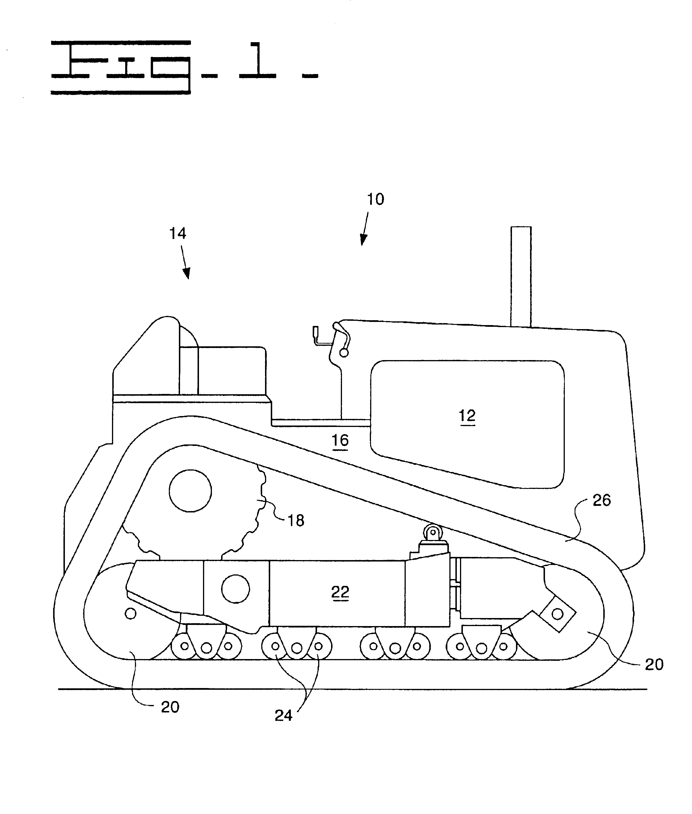
[0011]Referring to the drawings, specifically FIG. 1, a track type machine 10 is shown. The track type machine 10 includes an engine 12, an operator's station 14, a main frame 16, a drive sprocket assembly 18, and front and rear idler assemblies 20. The main frame 16 supports a track roller frame 22, with the idler assemblies 20 being rotatably attached thereto, as well as a plurality of supporting guide rollers 24. An endless track 26 is entrained around the drive sprocket 18, the idler assemblies 20 and the supporting guide rollers 24.

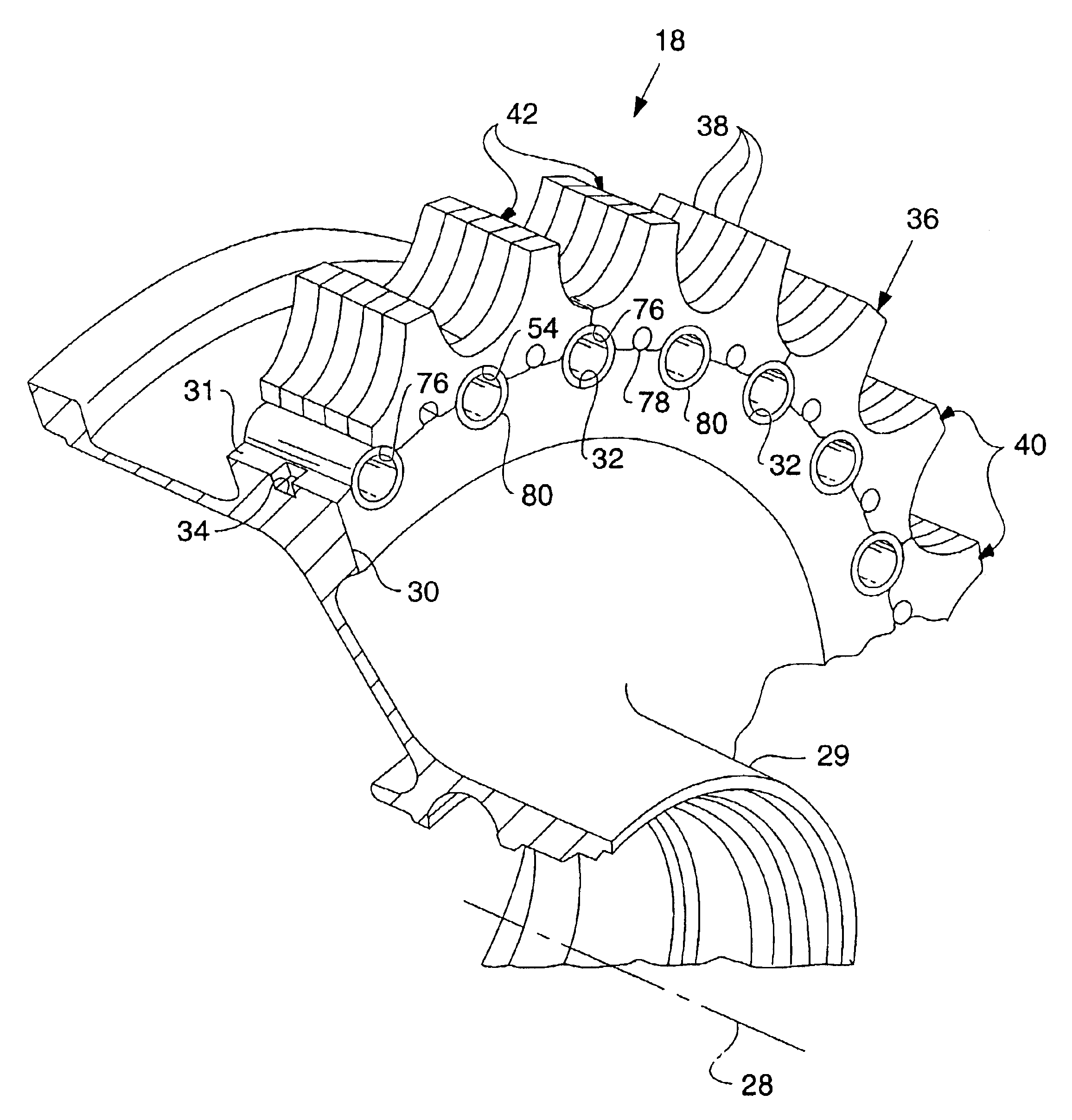
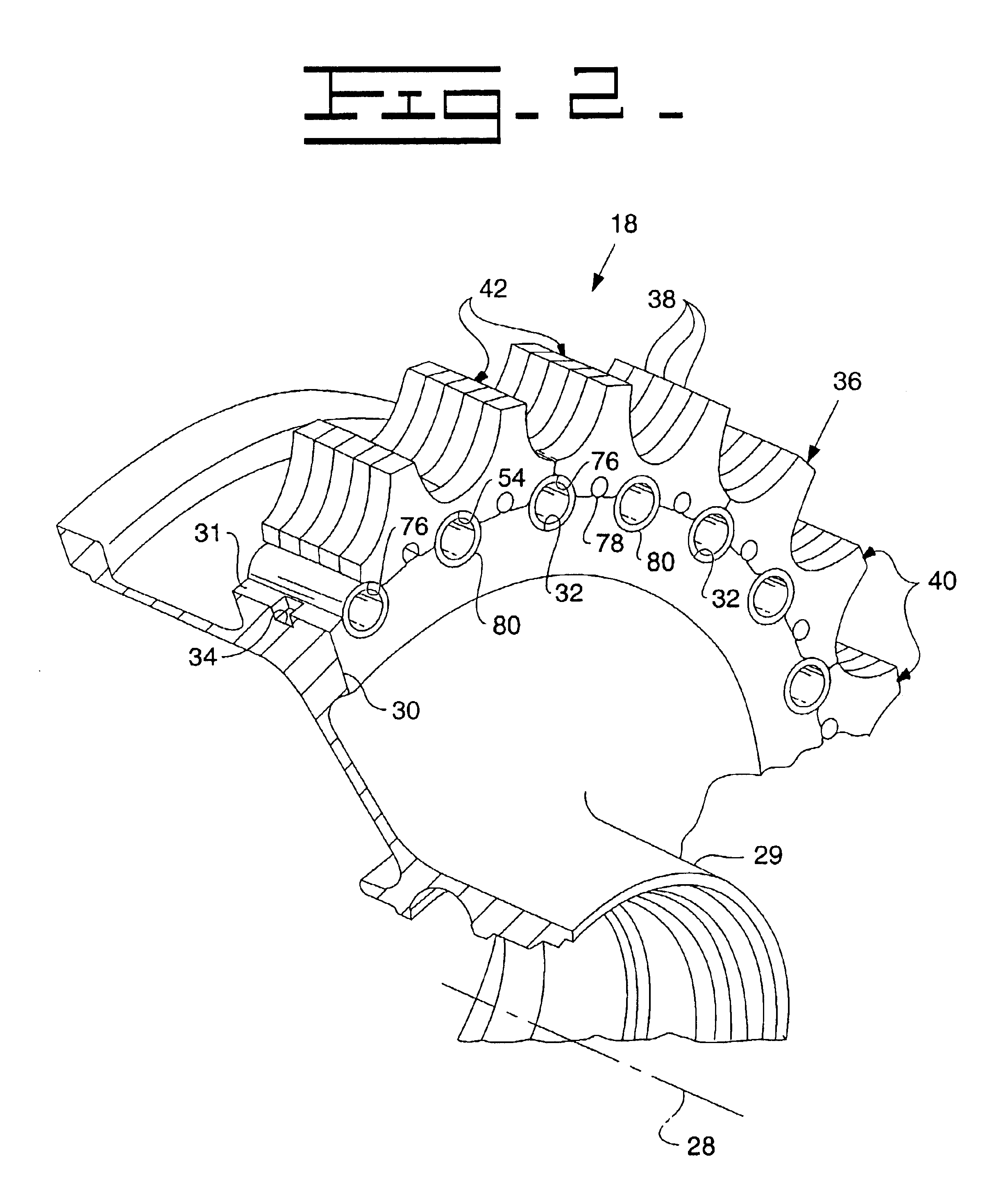
[0012]The drive sprocket assembly 18 embodying the present invention is illustrated in FIGS. 2-5. The drive sprocket assembly 18 rotates about an axis of rotation 28 and has a centrally disposed hub portion 29 that has an annular flange 30 disposed about an outer peripheral surface 31 of the hub 29. The flange 30 has an outer peripheral surface 31 with a plurality of spaced slots 32, which extend in a direction parallel with the axis 28 of the drive ...


PUM


Abstract

A drive sprocket assembly includes a hub having an endless chain connected thereto. A plurality of driver members are mounted between the hub and the endless chain to provide sound suppression.

Description

TECHNICAL FIELD[0001]The present invention relates to track-type work machines, and more particular to a sprocket that has teeth mounted on a hub by compressible driving members.BACKGROUND[0002]Environmental regulations, in both the United States and other countries, are increasingly being directed to the suppression of noise emitted by construction machines such as track-type work machines. In track-type work machines undercarriage components are frequently major contributors to the overall noise of the machine. The undercarriage components include endless track chains, drive sprockets, idler wheels and track rollers.[0003]A great amount of effort has been directed to noise abatement in undercarriage assemblies. For example, U.S. Pat. No. 4,881,930 issued Nov. 21, 1989 to Thomas E. Oertley describes an endless track sprocket assembly having a plurality of individually replaceable teeth structures with each tooth structure being resiliently isolated from adjacent tooth structures an...

Claims


Application Information

Patent Timeline
IPC IPC(8): F16H55/12F16H55/02
CPCF16H55/12
Inventor OERTLEY, THOMAS E.
Owner CATERPILLAR INC
Why Eureka
Eureka Blog
Learn More