Lens attachment combined with formation of eye glasses frame
a technology of lens attachment and eye glasses frame, applied in the field of eyewear, can solve the problems of limited resiliency, secure attachment of lenses to eye glasses frame, and substantially rigid eye glasses frame plastic frame, and achieve the effect of avoiding the possibility of lenses being los
- Summary
- Abstract
- Description
- Claims
- Application Information
AI Technical Summary
Benefits of technology
Problems solved by technology
Method used
Image
Examples
first embodiment
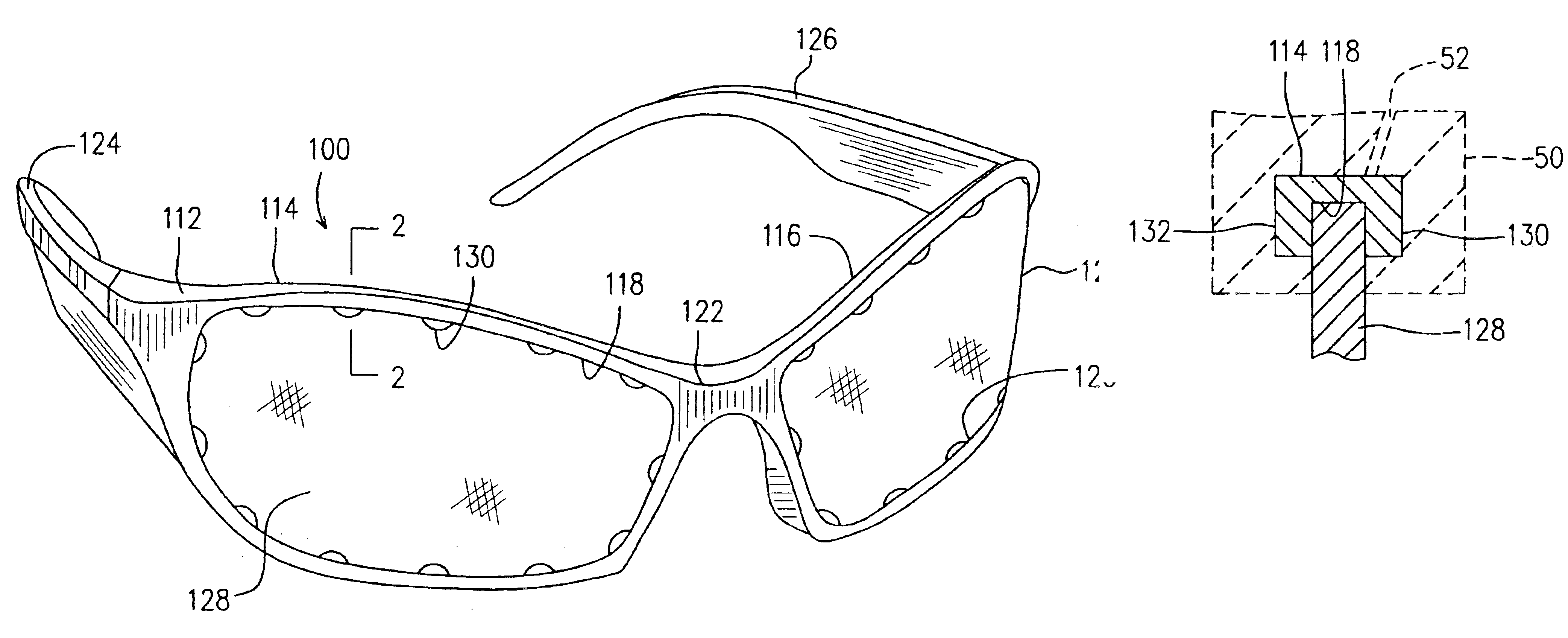
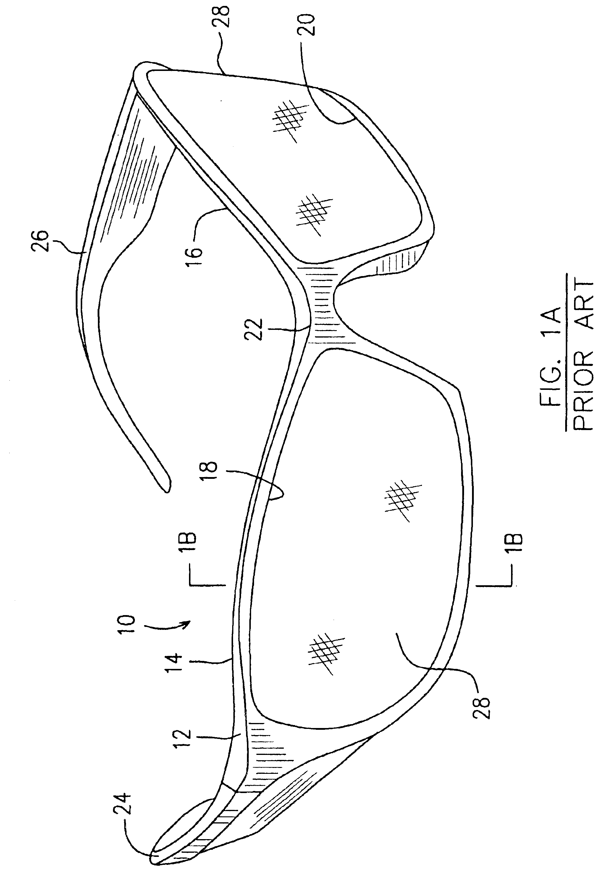
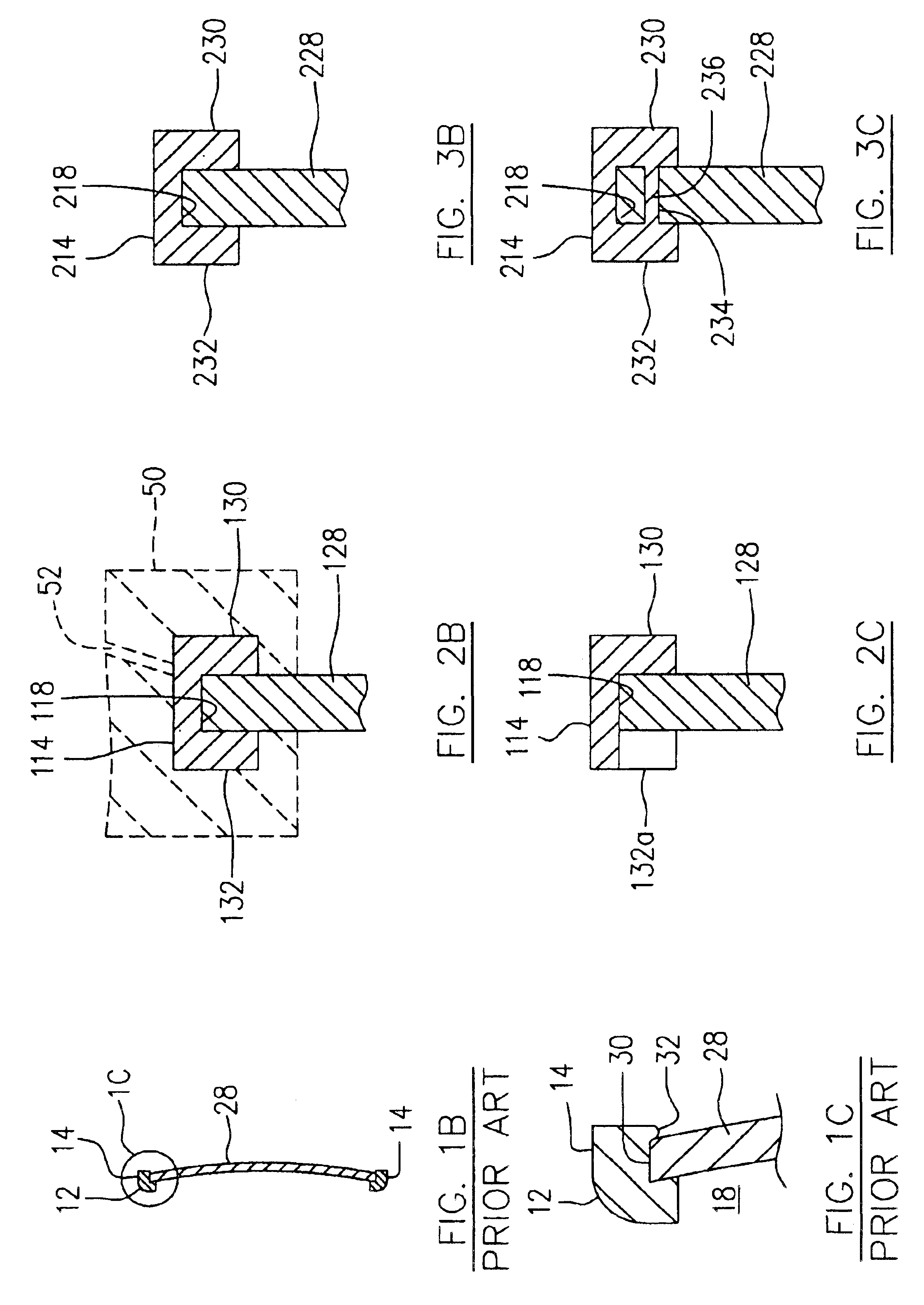
[0032]FIGS. 2A-2C illustrate a pair of eye glasses indicated by numeral 100 in accordance with the present invention. The eye glasses 100 are used as an example to illustrate one embodiment of the present invention. Nevertheless, any other type of eye glasses which includes substantially rigid plastic frame bodies and substantially rigid lenses, such as prescription eye glasses, protective work glasses, sunglasses, etc. is included in the concept of the present invention as illustrated by the embodiment 100 and in further embodiments to be described hereinafter.
[0033]The eye glasses 100 include a frame structure 112 made of a substantially rigid plastic material. The frame structure 112 generally includes two frame bodies 114, 116, defining apertures 118, 120 therein, respectively. A bridge 122 interconnects the two frame bodies 114 and 116 and extends between the inner ends thereof. A pair of temples 124, 126 of the same substantially rigid plastic material are pivotally attached t...
second embodiment
[0039]FIGS. 3A-3C illustrate the present invention in which a pair of eye glasses 200 is similar to the pair of eye glasses 100 of FIG. 2A. The components of eye glasses 200 are indicated using numerals in the 200 series with the last two digits corresponding to similar components in the 100 series illustrated in FIG. 2A, and will not therefore be redundantly described. The embodiment shown in FIG. 3A is a further development of the embodiment shown in FIG. 2A. When the retaining members 130 and 132 of the eye glasses100 (as shown in FIGS. 2A and 2B), are connected adjacent to one another in each of the first and second groups, these retaining members substantially form opposed continuous side walls 230, 232 extending into the aperture 218 of the eye glasses 200, thereby defining a continuous channel therebetween (not indicated). The continuous channel defined between the opposed side walls 230, 232 is configured to correspond to the periphery of the lens 228 for receiving the perip...
third embodiment
[0044]FIG. 4A illustrates the present invention in which a pair of eye glasses 300 having components similar to those of the eye glasses 200 illustrated in FIG. 3A. The similar components of eye glasses 300 are indicated by numerals in the 300 series with the last two digits similar to those indicating corresponding components of the eye glasses 200 in FIG. 3A, and will not therefore be redundantly described. The difference between the eye glasses 300 and the eye glasses 200 of FIG. 3A lies in that, instead of having opposed continuous side walls 230, 232 of FIG. 33 defining a continuous channel surrounding the entire periphery of lens 228, the frame body 314 of eye glasses 300 includes an upper section of a channel defined between an upper front side wall 320a and an upper rear side wall (behind the lens 328 and not shown) and a lower channel defined between a lower front side wall 320b and a lower rear side wall (behind the lens 328 and not shown). An upper section of the lens 328...
PUM
| Property | Measurement | Unit |
|---|---|---|
| Diameter | aaaaa | aaaaa |
| Size | aaaaa | aaaaa |
| Dimension | aaaaa | aaaaa |
Abstract
Description
Claims
Application Information
 - R&D
- Intellectual Property
- Life Sciences
- Materials
- Tech Scout
- Unparalleled Data Quality
- Higher Quality Content
- 60% Fewer Hallucinations
Browse by: Latest US Patents, China's latest patents, Technical Efficacy Thesaurus, Application Domain, Technology Topic, Popular Technical Reports.
© 2025 PatSnap. All rights reserved.Legal|Privacy policy|Modern Slavery Act Transparency Statement|Sitemap|About US| Contact US: help@patsnap.com


