
Reciprocating pump control system

Inactive Publication Date: 2005-05-10
1123050 ALBERTA +1
View PDF16 Cites 41 Cited by
  • Summary
  • Abstract
  • Description
  • Claims
  • Application Information

AI Technical Summary

Benefits of technology

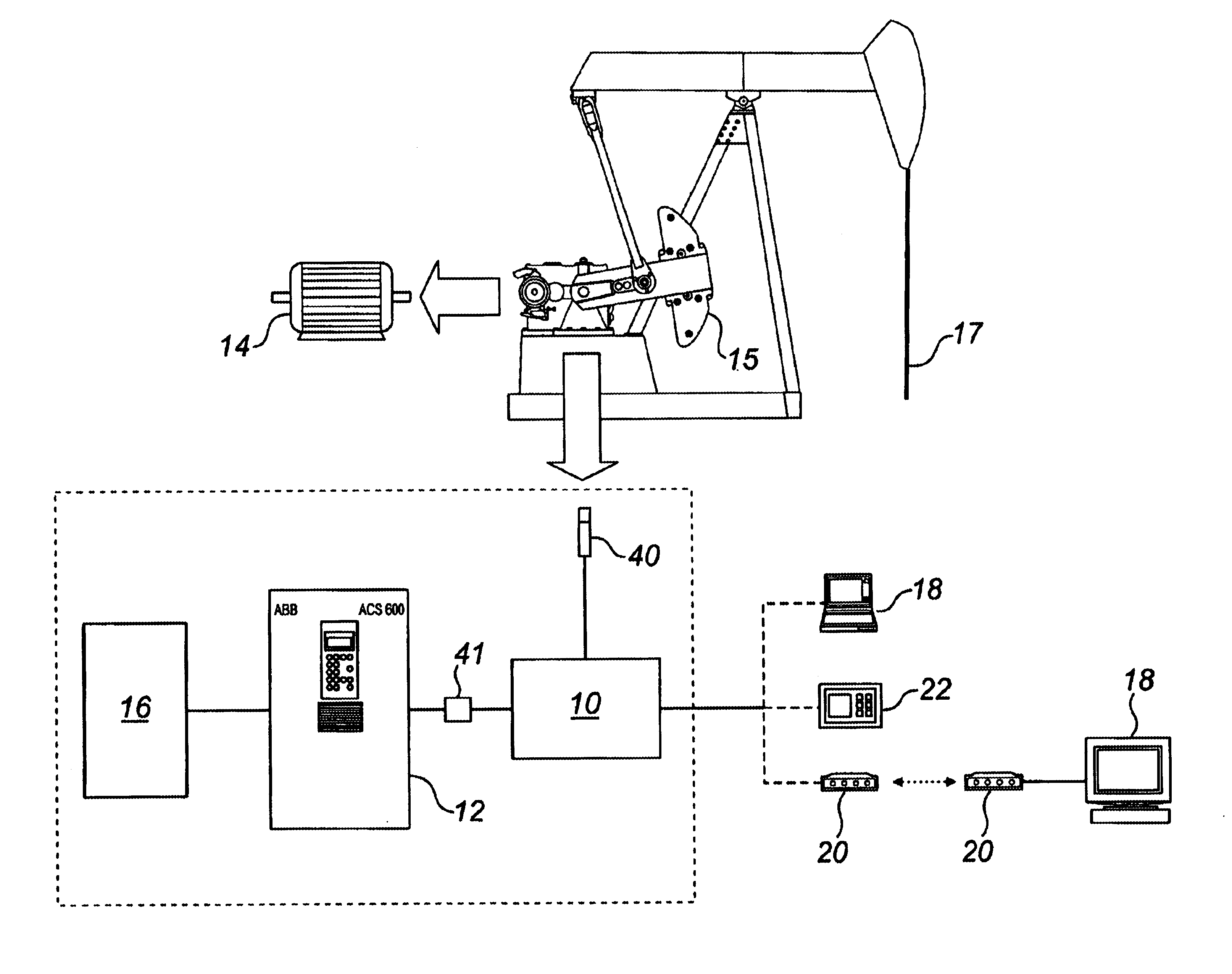
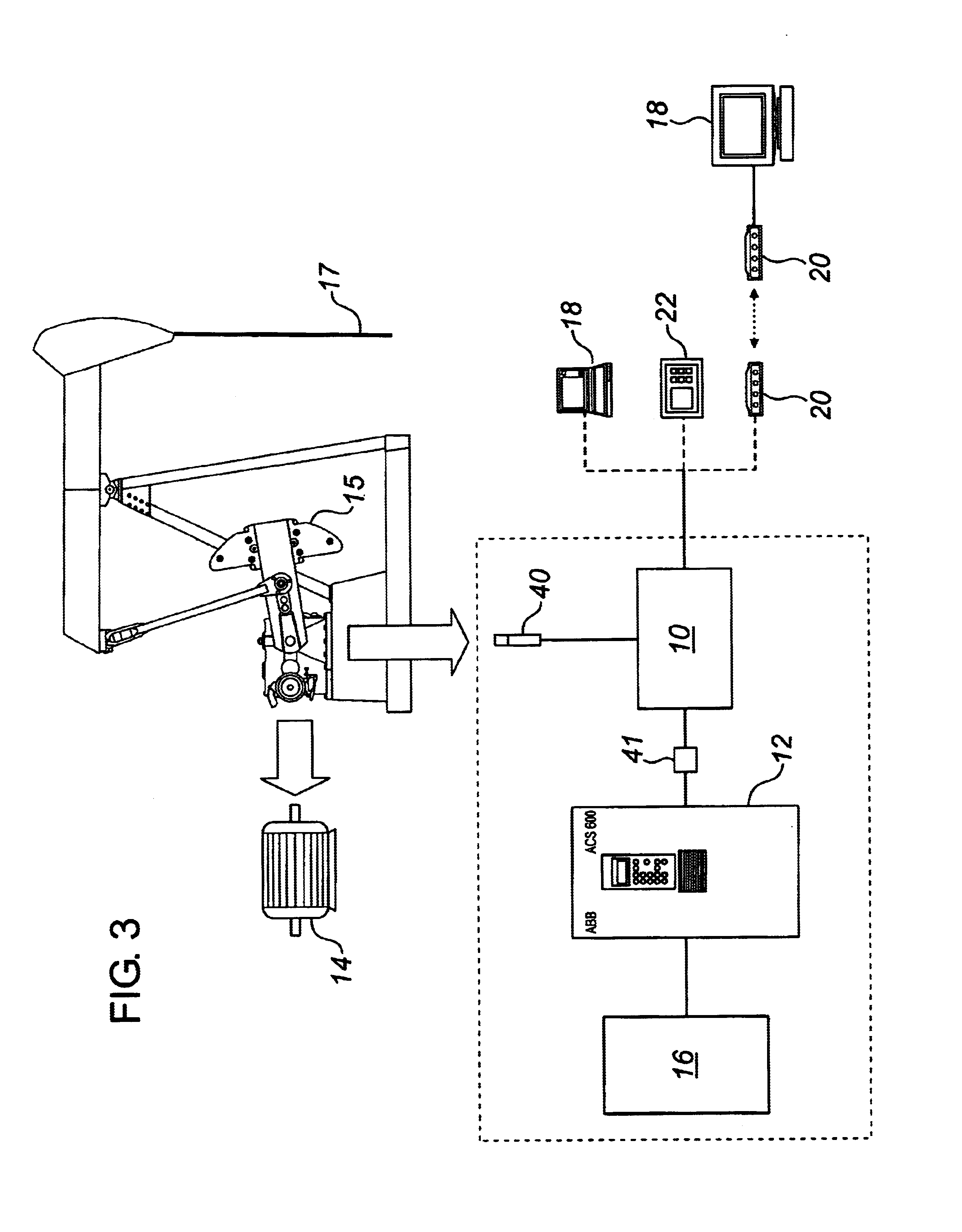
[0006]In general terms, the invention comprises a speed control system for a rocking beam pump that is driven by an electric or internal combustion motor. The system enables a user to control the dynamics of the pumping process by adjusting to compensate for the geometry of the pumping unit. In essence, the dynamics and motion of the rod strin

Problems solved by technology

However, no detailed disclosure of the control system is provided.
As well, the system does not allow for customized speed profiles to be implemented.

Method used


Image

  • Reciprocating pump control system
  • Reciprocating pump control system
  • Reciprocating pump control system

Examples


Embodiment Construction

[0028]The present invention provides for a speed control system for a walking beam pumping unit that is driven by an electric or internal combustion motor. When describing the present invention, all terms not defined herein have their common art-recognized meanings.

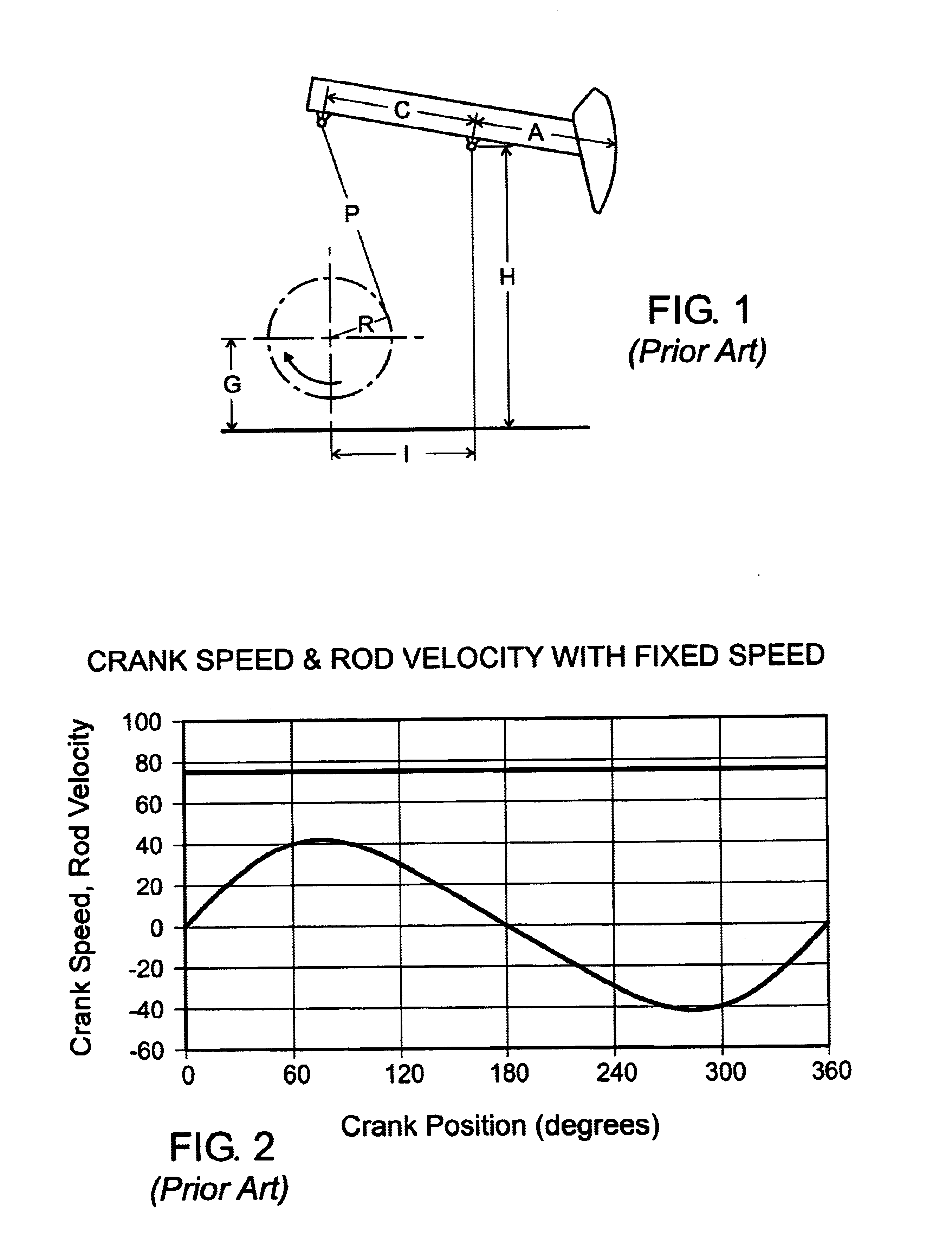
[0029]A conventional walking beam pumping unit is shown in FIG. 1. As is well known in the art, the geometry of the pumping unit translates rotational motion of the crank arm to vertically linear reciprocating motion of the polished rod and the sucker rods. The geometry of the pumping unit is determined by the measurements of the distances indicated by A, C, P, R, G and H shown in FIG. 1. As used herein, a single pumping cycle of such a pumping unit is defined by one complete revolution of the crank arm. A single pumping cycle may be deemed to start at a point where the rod string has reached its lowest point and continues as the rod string ascends, reverses and decends back to its starting position. Assuming a constant c...


PUM


Abstract

A pumpjack speed control system includes a user interface, a controller and a variable speed drive. The user interface includes a mathematical representation of the pumpjack geometry which permits the conversion of rod speed profiles to crank speed profiles.

Description

FIELD OF THE INVENTION[0001]The present invention relates to a system for varying the speed of a rotationally-actuated, reciprocating pump. More particularly, it relates to a method and apparatus for controlling the intra-cycle rod speed of a pumpjack.BACKGROUND OF THE INVENTION[0002]Reciprocating pumps such as pumpjacks are typically operated with a fixed motor speed during a revolution of the crank arm. The speed, acceleration and position of the linear motion applied to the rod string at the horsehead are determined by the speed, acceleration and position of the crank arm and the geometry of the pumpjack. The geometry of a typical pumpjack is depicted in FIG. 1. Conventional operation of a pumpjack is to maintain a constant crank speed. As a result, the geometry of the pumpjack dictates a rod speed which follows a curve which is sinusoidal in nature.[0003]Adjustments to optimize well production have historically involved changing the geometry of the pump or by increasing or decre...

Claims


Application Information

Patent Timeline
IPC IPC(8): F04B47/02F04B49/06F04B47/00
CPCF04B47/022F04B49/065F04B2201/0202F04B2203/0209F04B2203/0204F04B2203/0207F04B2201/1201
Inventor WATSON, JEFFAGGARWAL, RAMESHUPADHYAY, HARI
Owner 1123050 ALBERTA
Learn More