Refrigeration cycle apparatus

a technology of refrigerating cycle and apparatus, which is applied in the direction of domestic cooling apparatus, lighting and heating apparatus, machine operation mode, etc., can solve the problems of insufficient recovery of power which could have been recovered, difficulty in maintaining optimal cop when the operation condition is met, and increase in the amount of refrigerant flowing through the bypass pipe, etc., to achieve efficient recovery of power, and increase the flow rate of refrigerant

Inactive Publication Date: 2005-04-19
PANASONIC CORP
View PDF11 Cites 15 Cited by
  • Summary
  • Abstract
  • Description
  • Claims
  • Application Information

AI Technical Summary

Benefits of technology

[0013]According to this aspect, when it is necessary to increase the flow rate of refrigerant without changing the number of rotation of the expander, it is possible to increase the flow rate of refrigerant per one expansion process by introducing refrigerant from the injection circuit, and it is possible to recover power efficiently.
[0014]According to a second aspect of the invention, in the first aspect, the apparatus further comprises an adjusting valve for adjusting an amount of refrigerant from the injection circuit. By controlling the amount of refrigerant from the injection circuit, it is possible to optimally adjust the amount of refrigerant per one expansion process, and to recover power efficiently.
[0015]According to a third aspect of the invention, in the first aspect, the expander is provided at its refrigerant-inflow side with a pre-expansion valve. When it is necessary to reduce the amount of refrigerant without changing the number of rotation of the expander, it is possible to reduce the flow rate of refrigerant per one expansion process by reducing the opening of the pre-expansion valve.
[0016]According to a fourth aspect of the invention, in the first aspect, the expander is provided at its refrigerant-inflow side with a sub-expander. By pre-expansion is carried out by the sub-expander, it is possible to adjust a state of refrigerant in the inlet of the expander, and to optimally adjust the amount of refrigerant flowing through the expander. Therefore, it is possible to efficiently recover power in the expander, and to recover the expansion power also in the sub-expander which carries out the pre-expansion.
[0017]According to a fifth aspect of the invention, in the first aspect, the expander is provided at its refrigerant-outflow side with a sub-expander. It is possible to additionally expand by the sub-expander, and to optimally control the pressure in the outlet of the expander. Therefore, it is possible to efficiently recover power in the expander, and to recover the expansion power also in the sub-expander which carries out the additional expansion.
[0019]By changing torque of the electric generator of the sub-expander, it is possible to change the amount of refrigerant flowing through the sub-expander, and to adjust the amount of refrigerant flowing through the expander such that the optimal COP can be obtained.

Problems solved by technology

However, when the refrigeration cycle apparatus is provided with the expander and power recover by the expander is used as a portion of a driving force of the compressor, the number of rotation of the expander and the number of rotation of the compressor must be the same, and in the expander which is designed optimally with a predetermined density ratio, it is difficult to maintain the optimal COP when the operation condition is changed.
However, there is a problem that as a difference between an amount of refrigerant which flows into the expander and an optimal flow rate in terms of design is increased, an amount of refrigerant flowing through the bypass pipe is increased and as a result, power which could have been recovered can not sufficiently recover.

Method used


Image

  • Refrigeration cycle apparatus
  • Refrigeration cycle apparatus
  • Refrigeration cycle apparatus

Examples


Embodiment Construction

[0037]A refrigeration cycle apparatus according to an embodiment of the present invention will be explained with reference to the drawings below.

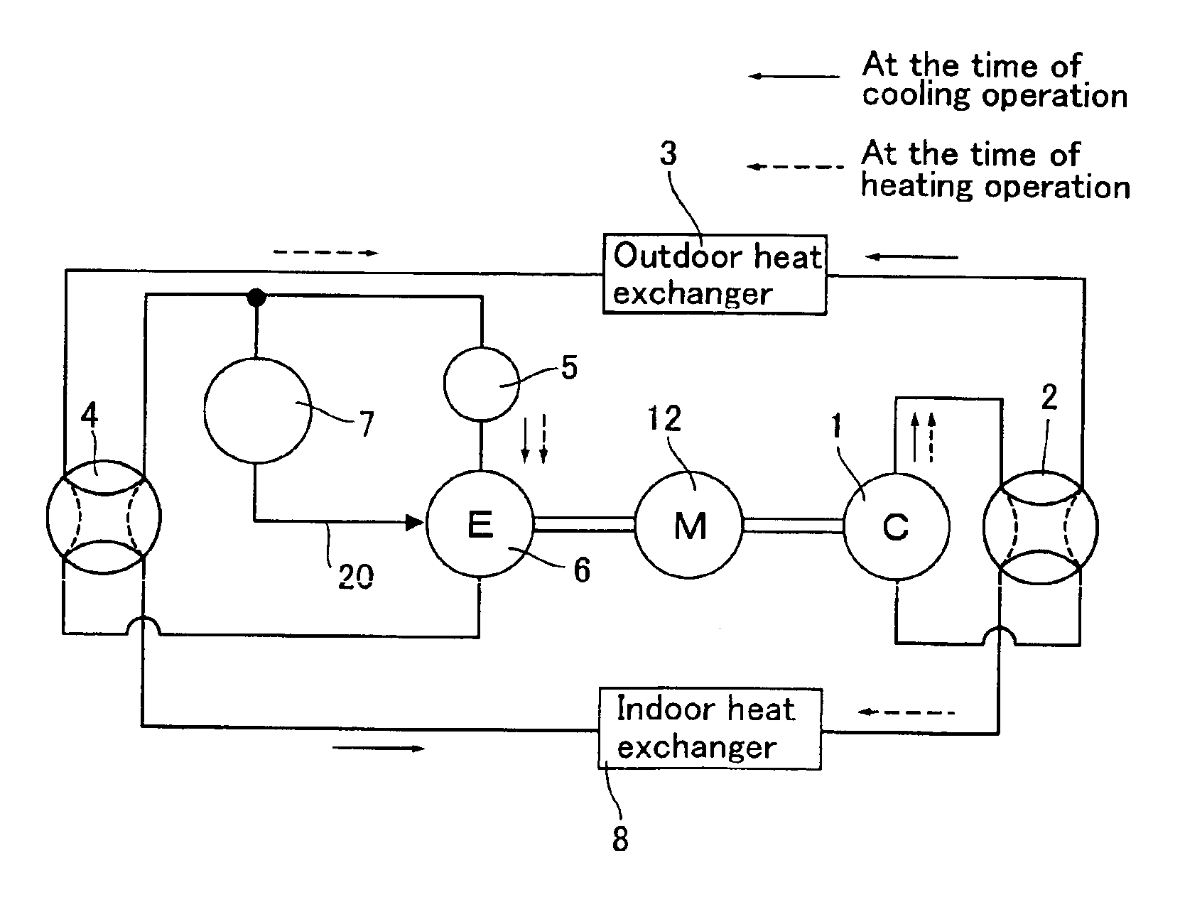
[0038]FIG. 1 shows a structure of the heat pump type air conditioner of the present embodiment.

[0039]As shown in FIG. 1, the heat pump type air conditioner of this embodiment uses CO2 refrigerant as refrigerant, and has refrigerant circuit. The refrigerant circuit comprises a compressor 1 having a motor 12, an outdoor heat exchanger 3, an expander 6 and an indoor heat exchanger 8 which are all connected to one another through pipes.

[0040]The expander 6 is provided at its inflow side with a pre-expansion valve 5.

[0041]The refrigerant circuit is provided with an injection circuit 20. The injection circuit 20 introduces high pressure refrigerant on the side of an outlet of the outdoor heat exchanger 3 in a halfway of the expansion process of the expander 6. The injection circuit 20 is provided with an adjusting valve 7 which adjusts an amount ...


PUM


Abstract

It is an object of the present invention to reduce the constraint that the density ratio is constant as small as possible, and to obtain high power recovering effect in a wide operation range. A refrigeration cycle apparatus uses carbon dioxide as refrigerant and has a compressor, an outdoor heat exchanger, an expander and an indoor heat exchanger. An injection circuit for introducing high pressure refrigerant is provided in a halfway of an expansion process of said expander.

Description

TECHNICAL FIELD[0001]The present invention relates to a refrigeration cycle apparatus using carbon dioxide as refrigerant and having a compressor, an outdoor heat exchanger, an expander and an indoor heat exchanger.BACKGROUND TECHNIQUE[0002]A flow rate of refrigerant which circulates through a refrigeration cycle apparatus is all the same in any points in a refrigeration cycle. If a suction density of refrigerant passing through a compressor is defined as DC and a suction density of refrigerant passing through an expander is defined as DE, the DE / DC (density ratio) is always constant.[0003]In recent years, attention is focused on a refrigeration cycle apparatus using, as refrigerant, carbon dioxide (CO2, hereinafter) in which ozone destroy coefficient is zero and global warming coefficient is extremely smaller than Freon. The CO2 refrigerant has a low critical temperature as low as 31.06° C. When a temperature higher than this temperature is utilized, a high pressure side (outlet of...

Claims


Application Information

Patent Timeline
Patent Type & Authority Patents(United States)
IPC IPC(8): F25B9/06F25B13/00F25B9/00F25B1/10F25B1/00F25B11/02F25B41/04
CPCF25B9/008F25B13/00F25B9/06F25B1/10F25B2309/061
Inventor NAKATANI, KAZUOKAWABE, YOSHIKAZUINOUE, YUJIOKAZA, NORIHOHIWATA, AKIRA
Owner PANASONIC CORP
Why Eureka
Try Eureka