
Device for controlling signal bands in a packet network

a packet network and signal band technology, applied in the field of atm multiplexing, can solve the problem that the band cannot be dynamically varied, and achieve the effect of reducing the amount of wasted band, and efficient use of band capacity

Inactive Publication Date: 2005-04-05
FUJITSU LTD
View PDF12 Cites 22 Cited by
  • Summary
  • Abstract
  • Description
  • Claims
  • Application Information

AI Technical Summary

Benefits of technology

[0014]This invention solves the problem described above. It provides a device that can efficiently use band capacity for the signal channel in a packet network.
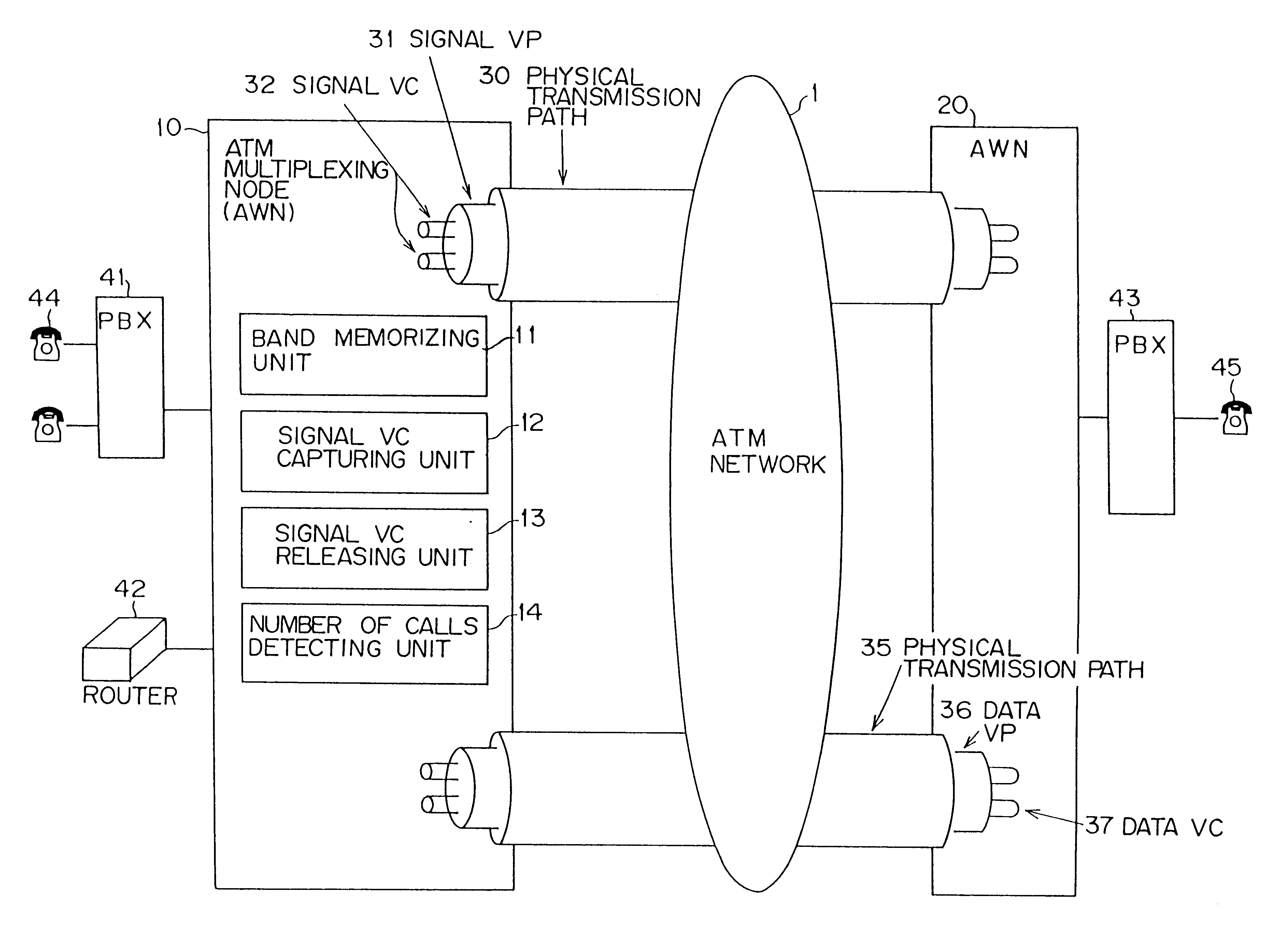
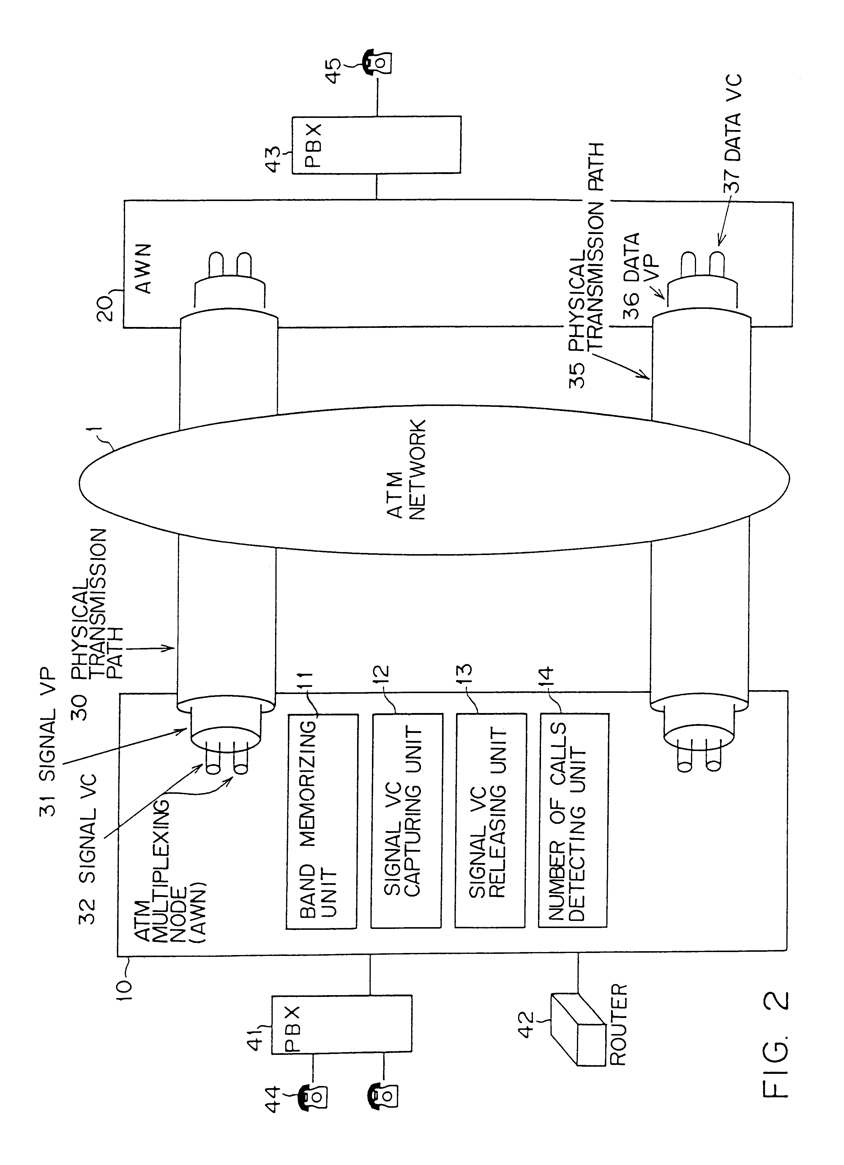
[0017]In the configuration described above, the capturing means secures the smallest necessary signal band for each call origination. The releasing means releases the unnecessary band when it is no longer needed for the signal. For this reason, the amount of wasted band is decreased, which makes for efficient use of band capacity.
[0018]In addition to the basic configuration described above, reassignment means for, if the number of calls assigned to a first signal channel drops below a predetermined threshold, assigning a call that had been assigned to that first signal channel to a second signal channel may be provided, so that the releasing means can release the first signal channel. In this kind of configuration, in a case in which the number of calls assigned to a certain signal VC (the old VC) is small, those calls are assigned to another-signal VC, and the old VC is released. For this reason, the band capacity that had been assigned to the old VC can be assigned to another medium, making for efficient use of band capacity.
[0019]In addition to the basic configuration described above, learning means for monitoring communication conditions under certain predetermined condition and establishing means for establishing a signal channel that has a band corresponding to the communication conditions detected by the learning means under the predetermined condition may be provided. In this kind of configuration, it is possible to automatically set signal bands in accordance with the communication condition monitored using the learning means, decreasing the amount of work involved in supervising band operation.

Problems solved by technology

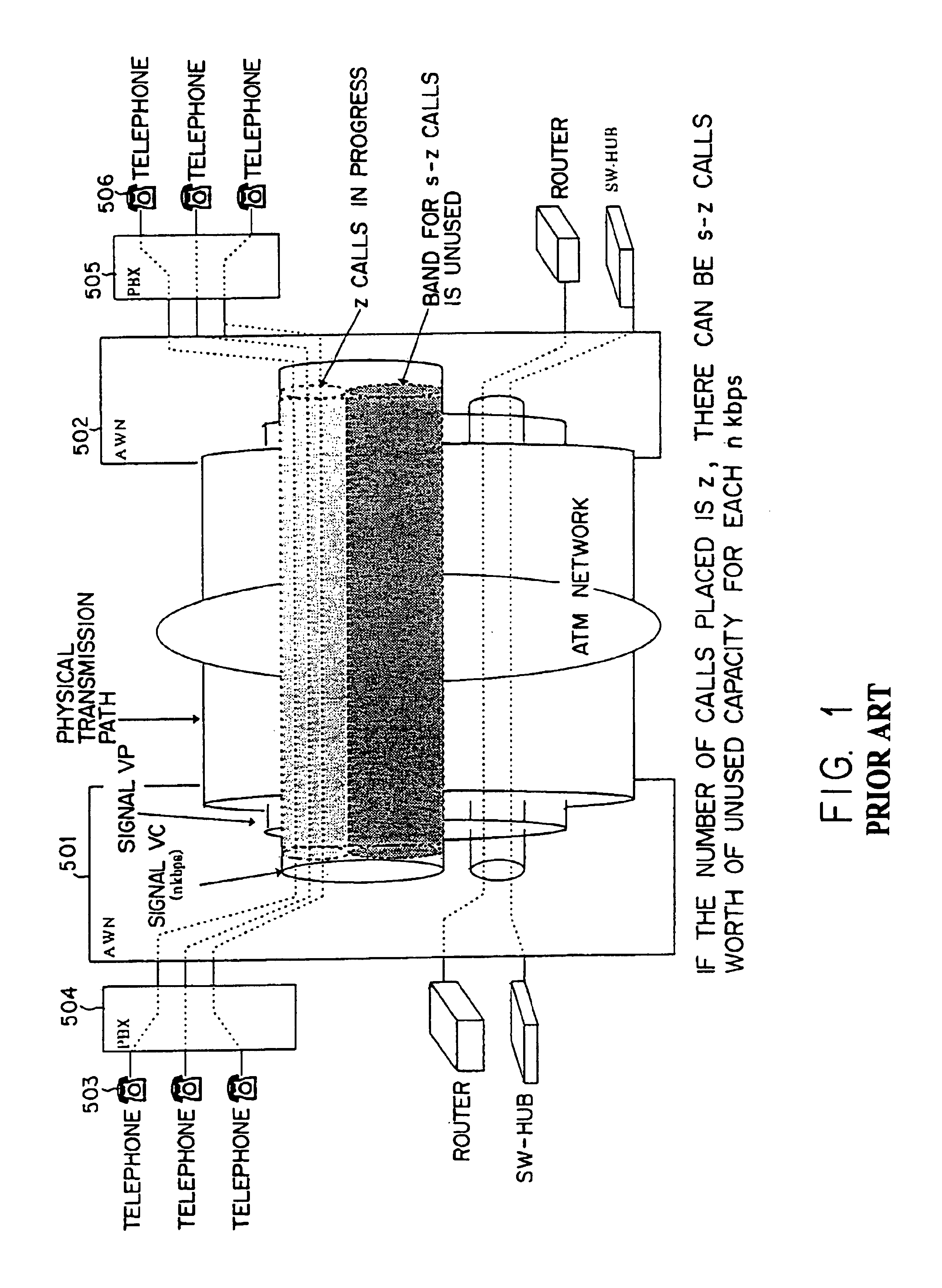
However, in an existing system, once the band (capacity) for each signal VC is first set, that band cannot be dynamically varied.

Method used


Image

  • Device for controlling signal bands in a packet network
  • Device for controlling signal bands in a packet network
  • Device for controlling signal bands in a packet network

Examples


Embodiment Construction

29 is a flowchart of the learning processing for each day of the week;

[0054]FIG. 30 is a flowchart of the learning processing for each date;

[0055]FIG. 31 is a flowchart of the learning selection processing;

[0056]FIG. 32 is a flowchart (1 of 2) of the processing to avoid duplicate capture of a signal band;

[0057]FIG. 33 is a flowchart (2 of 2) of the processing to avoid duplicate capture of a signal band;

[0058]FIG. 34 is a flowchart of the processing in the ATM multiplexing node that receives messages sent by the processing in the flowcharts in FIG. 32 and FIG. 33;

[0059]FIG. 35 shows a configuration diagram of the VPI / VCI supervision table;

[0060]FIG. 36 is a flowchart (1 of 2) of the processing to switch service categories;

[0061]FIG. 37 is a flowchart (2 of 2) of the processing to switch service categories;

[0062]FIG. 38 is a flowchart of the band capture processing including a fixed band securing function;

[0063]FIG. 39 is a flowchart of the processing to select the band capture method...


PUM


Abstract

A first ATM multiplexing node is connected to a second ATM multiplexing node via an ATM network. A number of calls detecting unit detects the number of voice calls set up on the transmission path that connects the first ATM multiplexing node to the second ATM multiplexing node. A signal VC capturing unit captures signal VCs in accordance with the additional number of voice calls detected by the number of calls detecting unit. A signal VC releasing unit releases signal VCs in accordance with the decrease in the number of calls detected by the number of calls detecting unit.

Description

BACKGROUND OF THE INVENTION[0002]1. Field of the Invention[0003]This invention relates to a device that controls bands assigned to signal channels in a packet network. In particular, it relates to an ATM multiplexing device that controls bands for virtual channels used for signalling in an ATM network.[0004]2. Description of the Related Art[0005]ATM is widespread as a core technology for making multimedia communication possible. In ATM, data are stored in fixed length packets called cells and transferred. A cell basically consists of a 5-byte header and a 48-byte payload. A VPI / VCI (Virtual Path Identifier / Virtual Channel Identifier) is set in the header as routing information for each cell. The information to be transferred is stored in the payload. For this reason, ATM is able to handle various types of data such as audio data, video data and text data in a unified manner. In addition, in ATM control data are also stored in the cells and transferred.[0006]FIG. 1 is a configuration...

Claims


Application Information

Patent Timeline
Patent Type & Authority Patents(United States)
IPC IPC(8): H04L12/56H04L47/76
CPCH04L12/5601H04L2012/563
Inventor KISE, YUKIO
Owner FUJITSU LTD
Learn More