
Wood-type golf club head

Inactive Publication Date: 2005-04-05
SUMITOMO RUBBER IND LTD
View PDF10 Cites 93 Cited by
  • Summary
  • Abstract
  • Description
  • Claims
  • Application Information

AI Technical Summary

Benefits of technology

It is therefore, an object of the present invention to provide a wood-type golf club head, in which the design freedom is increa

Problems solved by technology

In such a golf club, as the club shaft is relatively long, it is difficult to control the motion of the club head at the time of hitting a ball.
As a result, it becomes difficult to return a club head to an expected position as shown in FIG. 7b at the time of hitting a ball.
However, in a large-sized club head, which has a very large head volume of over 400 cc in particular, t

Method used


Image

  • Wood-type golf club head
  • Wood-type golf club head
  • Wood-type golf club head

Examples


Example

Embodiments of the present invention will now be described in detail in conjunction with the accompanying drawings.

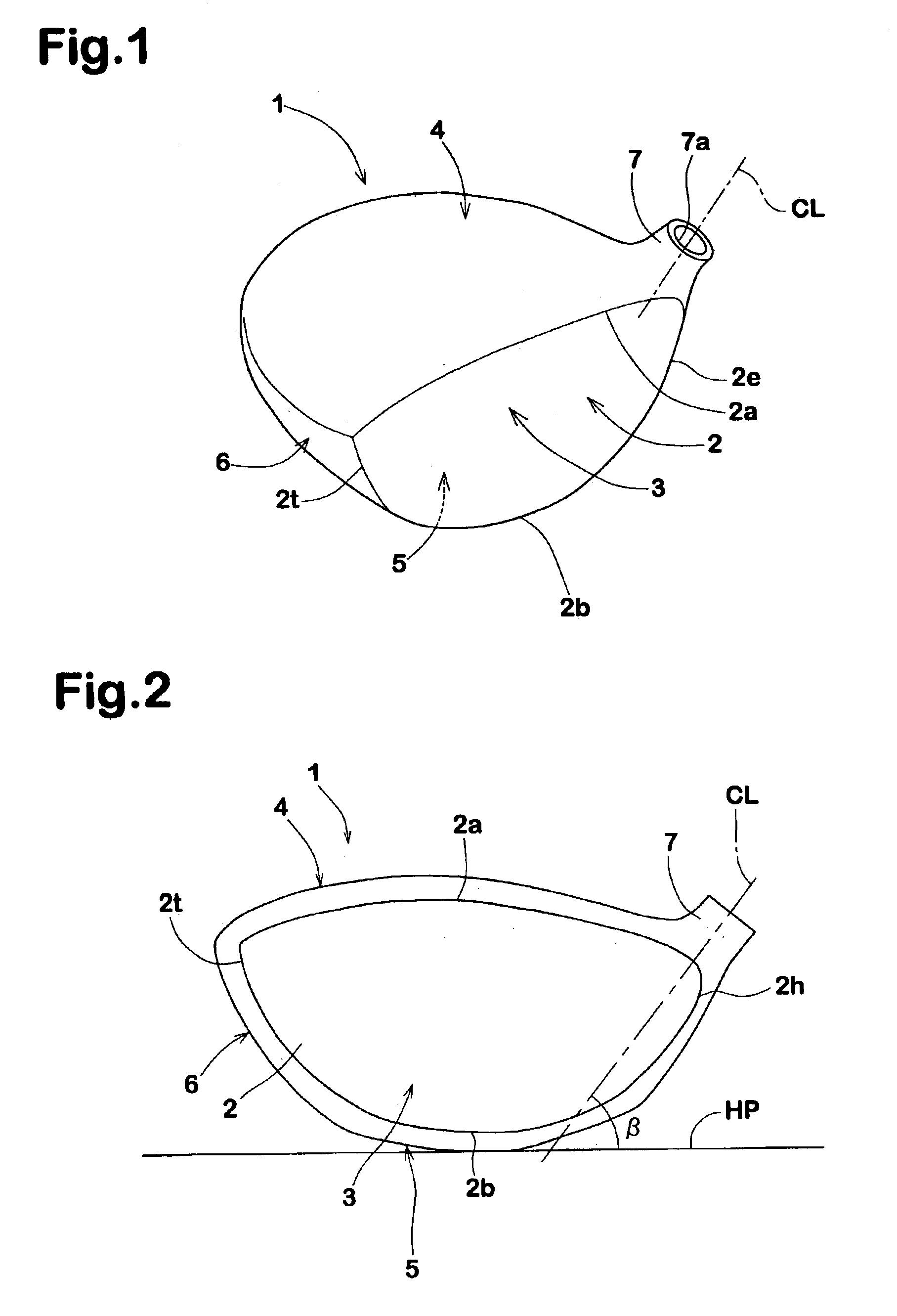
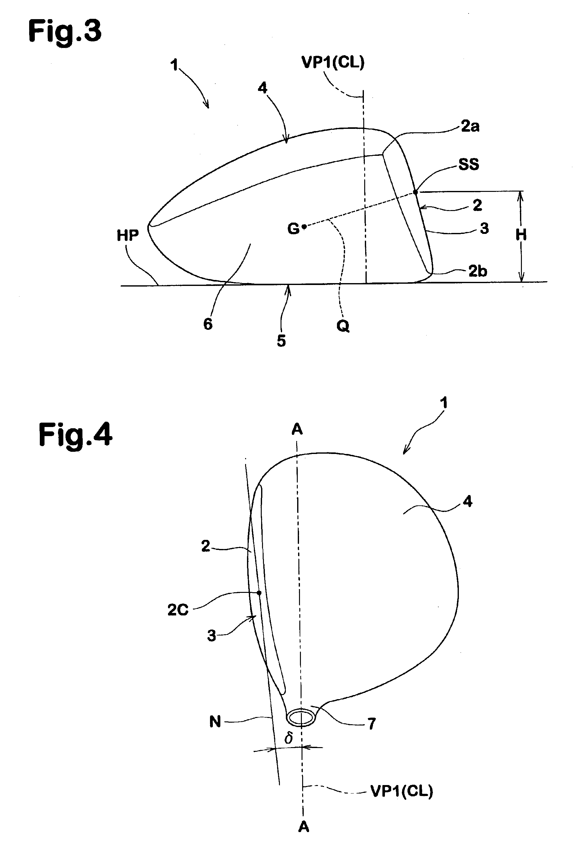
In the drawings, golf club head 1 according to the present invention is a hollow wood-type golf club head comprising a face portion 3 of which front face defines a clubface 2 for striking a ball, a crown portion 4 intersecting the clubface 2 at the upper edge 2a thereof, a sole portion 5 intersecting the clubface 2 at the lower edge 2b thereof, a sidewall portion 6 between the crown portion 4 and sole portion 5 which extends from a toe-side edge 2t to a heel-side edge 2e of the clubface 2 through the back face of the club head, and a neck portion 7 to be attached to an end of a club shaft (not shown).

The neck portion 7 is provided with a shaft inserting hole 7a having an opening for the club shaft at the upper end thereof. The neck portion 7 comprises an inner tubular part extended into the cavity (i). In this example, as shown in FIG. 5, the tubular part terminates in ...


PUM


Abstract

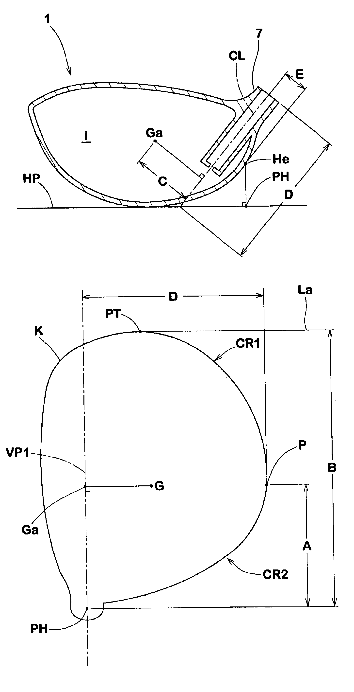
A wood-type golf club head which has a head volume of not less than 320 cc, a gravity point distance (C) in a range of from 25 to 35 mm, and a heel area width (A) in a range of from 30 to 52% of a clubhead width (B).

Description

This nonprovisional application claims priority under 35 U.S.C. § 119(a) on Patent Application No. 2002-10455 filed in JAPAN on Jan. 18, 2002, which is herein incorporated by reference.BACKGROUND OF THE INVENTIONThe present invention relates to a wood-type golf club head, more particularly to an improved configuration for a large-sized club head being capable of improving return motion of the head at the time of hitting a ball.In recent years, wood-type club heads for drivers and the like are increased in the volume, while preventing the weight from increasing, and club heads having a volume of more than 320 cc are widely used. In such a golf club, as the club shaft is relatively long, it is difficult to control the motion of the club head at the time of hitting a ball. On the other hand, the distance of the gravity point of the club head from the axis of the club shaft basically increases as the size of the club head becomes large. As a result, it becomes difficult to return a club...

Claims


Application Information

Patent Timeline
IPC IPC(8): A63B53/04A63B102/32
CPCA63B53/0466A63B2209/023A63B2053/0412A63B2053/0408A63B53/0412A63B53/0408
Inventor NISHIO, MASAYOSHI
Owner SUMITOMO RUBBER IND LTD
Learn More