
Molten metal pump system

a pump system and molten metal technology, applied in the direction of liquid fuel engines, marine propulsion, vessels, etc., can solve the problems of time-consuming and laborious replacement or service of a pump operating submerged in molten metal, corroding and deteriorating, and being one of the more difficult environments for maintaining a pump

Inactive Publication Date: 2005-03-22
PYROTECK INC
View PDF4 Cites 92 Cited by
  • Summary
  • Abstract
  • Description
  • Claims
  • Application Information

AI Technical Summary

Problems solved by technology

Molten metal may be one of the more difficult environments in which to maintain a pump due to the heat and corrosive factors within the molten metal.
Despite the positive properties for this application, graphite and ceramics still corrode and deteriorate over time, and molten metal pumps must be more frequently maintained and replaced than other types of pumps.
The replacement or servicing of a pump operating submersed in molten metal is a time consuming exercise.
First the pump must be removed from the molten metal which generally causes downtime of the metal furnace if that is the application.
However, when the pump must be disassembled, those cemented joints can be very difficult to disassemble.
This makes the disassembly much more difficult when certain replacement parts are being placed back into other parts which have already been in operation.
The combination of configuration and the number of components of typical pump systems makes them difficult to efficiently, accurately and quickly reassemble them.
The combination of the components are very heavy, and because there are as many as four components which must be accurately aligned and then secured to one another, substantial time must be taken to assemble the pump system in the precise manner required by the application.

Method used


Image

  • Molten metal pump system
  • Molten metal pump system
  • Molten metal pump system

Examples


Embodiment Construction

Many of the fastening, connection, manufacturing and other means and components utilized in this invention are widely known and used in the field of the invention described, and their exact nature or type is not necessary for an understanding and use of the invention by a person skilled in the art or science; therefore, they will not be discussed in significant detail. Furthermore, the various components shown or described herein for any specific application of this invention can be varied or altered as anticipated by this invention and the practice of a specific application or embodiment of any element may already be widely known or used in the art or by persons skilled in the art or science; therefore, each will not be discussed in significant detail.

The terms “a”, “an”, and “the” as used in the claims herein are used in conformance with long-standing claim drafting practice and not in a limiting way. Unless specifically set forth herein, the terms “a”, “an”, and “the” are not lim...


PUM

PropertyMeasurementUnit
corrosiveaaaaaaaaaa
timeaaaaaaaaaa
axial rotationaaaaaaaaaa

Abstract

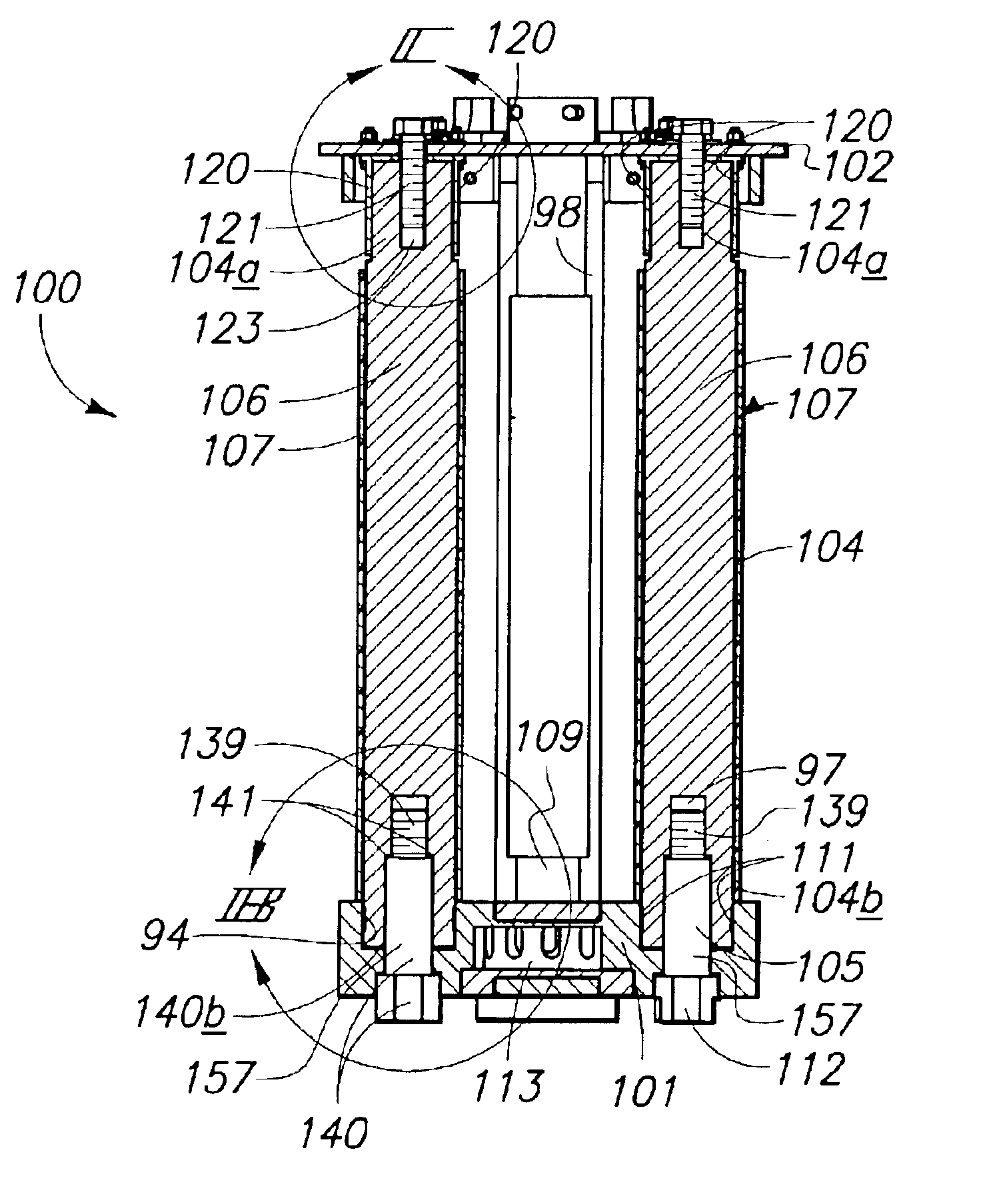
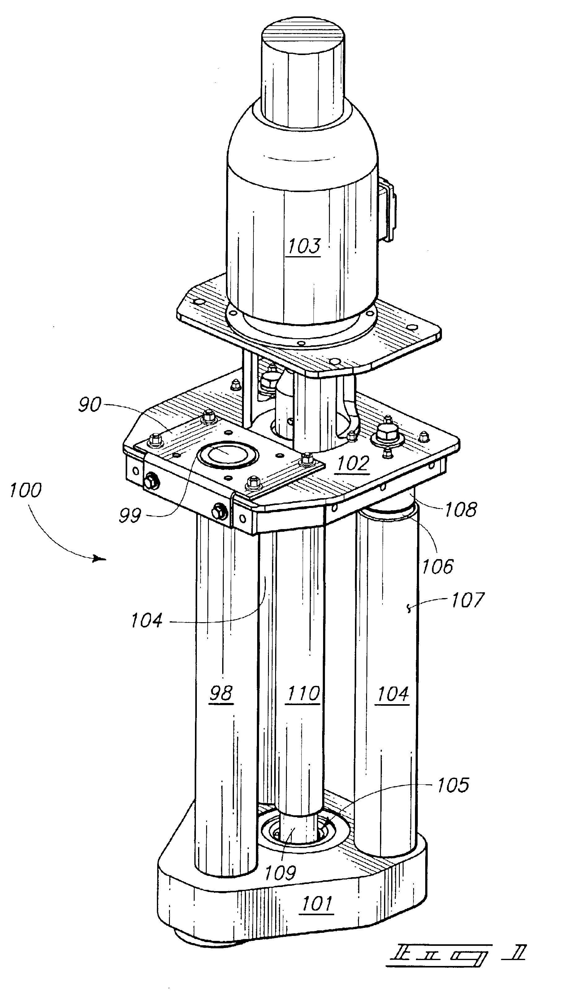
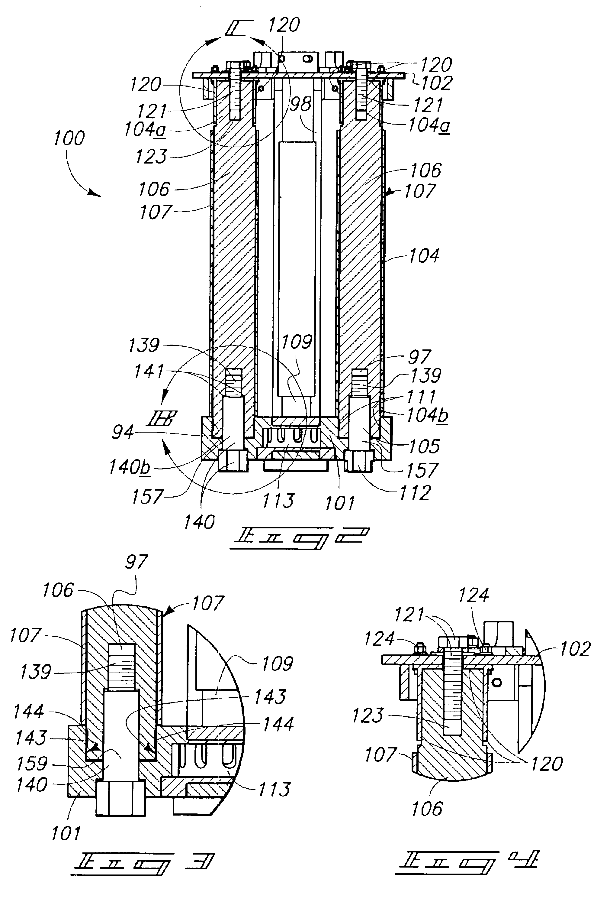
A molten metal pump system which generally provides a refractory connection joint for connecting a refractory pump post to a pump base, the pump post including a refractory post with a first end, the first end including an internally threaded joint screw aperture; a refractory base with a post aperture configured to receive the first end of the refractory post, and with a screw aperture contiguous with the post aperture; and a joint screw with a first end and a second end, the joint screw including a threaded external surface and a retention shoulder, the joint screw configured to insert through the screw aperture in the refractory base with the threaded external surface engaging the internally threaded joint screw aperture of the refractory post, and the retention shoulder engaging the refractory base.

Description

CROSS REFERENCE TO RELATED APPLICATIONThere are no applications related to this application or upon which priority is claimed.TECHNICAL FIELDThis invention pertains to a molten metal pump system for use in pumping molten metal, and more particularly, to joints and connections used with molten metal pumps to avoid the need for cemented joints.BACKGROUND OF THE INVENTIONMolten metal may be one of the more difficult environments in which to maintain a pump due to the heat and corrosive factors within the molten metal. The submerged components of these pumps are typically made of graphite, ceramics or similar materials due to the ability of these types of material compositions to withstand the heat and corrosive effects of the molten metal environment. While references may be made herein to molten aluminum, this is only used to give an example and not to limit the invention to aluminum pumps, since the pump systems disclosed herein may be used for pumping other molten metals.Despite the...

Claims


Application Information

Patent Timeline
Patent Type & Authority Patents(United States)
IPC IPC(8): F04D7/00F04D7/06
CPCF04D7/065
Inventor GILBERT, RONALDPALMER, MARK
Owner PYROTECK INC
Learn More