
Anti-rotation method and apparatus for limiting rotation of cementing plugs

a technology of cement plugs and anti-rotation, which is applied in the direction of fluid removal, sealing/packing, borehole/well accessories, etc., can solve the problems of economic impact on the cost of the well, valuable time-consuming plug rotation, etc., and achieve the effect of preventing or preventing

Inactive Publication Date: 2005-03-22
HALLIBURTON ENERGY SERVICES INC
View PDF35 Cites 7 Cited by
  • Summary
  • Abstract
  • Description
  • Claims
  • Application Information

AI Technical Summary

Benefits of technology

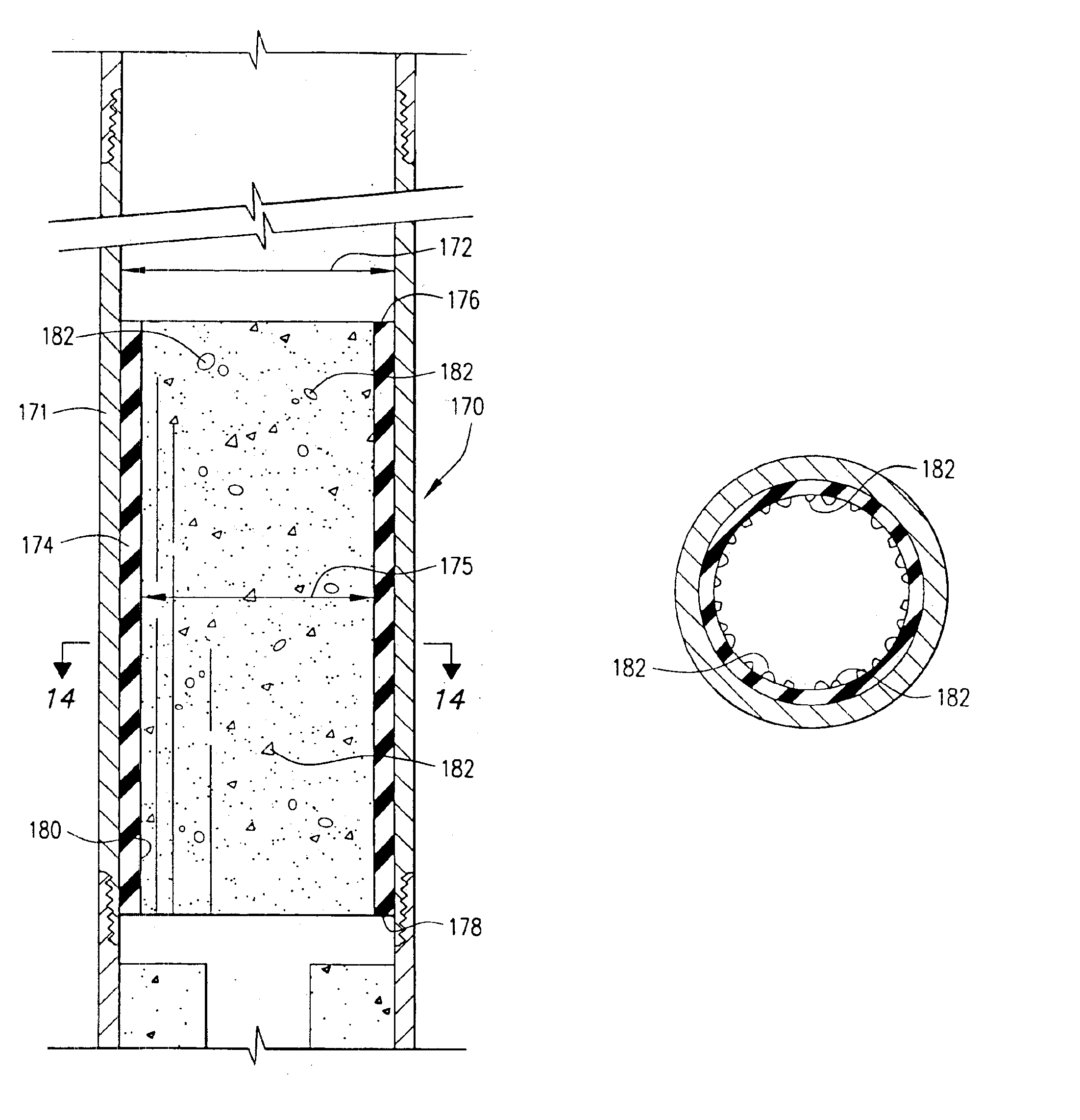
The present invention provides an apparatus for preventing, or at least limiting the rotation of a cementing plug during drillout of the cementing plug. The apparatus includes an outer case, which preferably is a joint of casing. The outer case may be referred to as an outer housing or outer sleeve. An inner sleeve is disposed in the outer case. The inner sleeve has an open upper end and an open lower end and is adapted to receive cementing plugs displaced through a casing string during a cementing job. The inner surface of the sleeve is configured and dimensioned so as to cause an interference fit, and thus frictionally engage cementing plugs that are received therein. Engagement between the cementing plugs and the inner sleeve will prevent or at least limit rotation of the cementing plugs during drillout of the cementing plugs after a cementing job. The inner sleeves are preferably comprised of a durable, drillable material.
In one embodiment, the inner sleeve has a tapered inner surface. The tapered inner surface preferably tapers radially inwardly from the upper end of the inner sleeve to the lower end of the inner sleeve. The tapered inner surface may have a circular cross-section so that the inner surface has a generally frustoconical shape, or may define a polygonal cross-section, so that the inner surface defines a polyhedral shape. The apparatus of the present invention limits rotation of cementing plugs by engaging the plugs that are received therein so that when rotational drilling forces are applied, rotation of the plug is prevented or is at least limited.

Problems solved by technology

Plug rotation costs valuable time and therefore has an economic impact on the cost of the well.

Method used


Image

  • Anti-rotation method and apparatus for limiting rotation of cementing plugs
  • Anti-rotation method and apparatus for limiting rotation of cementing plugs
  • Anti-rotation method and apparatus for limiting rotation of cementing plugs

Examples


Embodiment Construction

Referring now to the drawings and more particularly to FIG. 1, a prior art cementing plug set 10 is shown. Plug set 10 includes a top cementing plug 15 and a bottom cementing plug 20. The plug set 10 is shown in a casing 25 being cemented into a wellbore 30. Plug set 10 is shown after bottom cementing plug 20 has landed on a landing platform 32 which may comprise a float collar, float shoe or other float equipment, or any other restriction which will allow bottom cementing plug 20 to land, but which will also allow fluid flow therethrough. Bottom cementing plug 20 comprises a body 36 defining a flow passage 38 therethrough. Typically, a rupturable member will be disposed across the top of flow passage 38 such that when bottom cementing plug 20 lands, increasing fluid pressure will cause the rupturable member to burst so that fluid, such as the cement slurry, can flow through flow passage 38. In FIG. 1, the rupturable member has already been ruptured to allow flow through flow passag...


PUM


Abstract

An apparatus for preventing or limiting the rotation of cementing plugs in a casing string during drillout. The apparatus includes an outer housing with a sleeve disposed therein. The sleeve has an inner surface configured to engage cementing plugs received therein to cause an interference fit. The sleeve will hold the cementing plugs when rotational forces, such as drilling forces, are applied so that during drillout, rotation of the cementing plug is prevented or is at least limited.

Description

BACKGROUND OF THE INVENTIONThe present invention relates generally to drilling and completion techniques for downhole wells, and more particularly to methods and apparatus for limiting the rotation of cementing plugs being drilled out of the plugs.In the construction of oil and gas wells, a wellbore is drilled into one or more subterranean formations or zones containing oil and / or gas to be produced. During a wellbore drilling operation, drilling fluid (also called drilling mud) is circulated through the wellbore by pumping it down the drill string, through a drill bit connected thereto and upwardly back to the surface to the annulus between the walls of the wellbore and the drill string. The circulation of the drilling fluid functions to lubricate the drill bit, remove cuttings from the wellbore as they are produced and to exert hydrostatic pressure on pressurized fluid contained formations penetrated by the wellbore whereby blowouts are prevented.In most instances, after the wellb...

Claims


Application Information

Patent Timeline
IPC IPC(8): E21B33/13E21B33/16
CPCE21B33/16E21B33/167
Inventor BADALAMENTI, ANTHONY M.
Owner HALLIBURTON ENERGY SERVICES INC
Learn More