
Tandem axle power divider assembly with inboard slip driveshaft connection

a technology of power divider assembly and drive shaft, which is applied in the direction of mechanical equipment, transportation and packaging, etc., can solve the problems increasing and requiring two separate parts. , to achieve the effect of reducing the number of parts needed to construct the drive shaft, reducing the cost and weight of the drive shaft and the time required for assembly

Inactive Publication Date: 2005-03-08
DANA AUTOMOTIVE SYST GRP LLC
View PDF20 Cites 39 Cited by
  • Summary
  • Abstract
  • Description
  • Claims
  • Application Information

AI Technical Summary

Benefits of technology

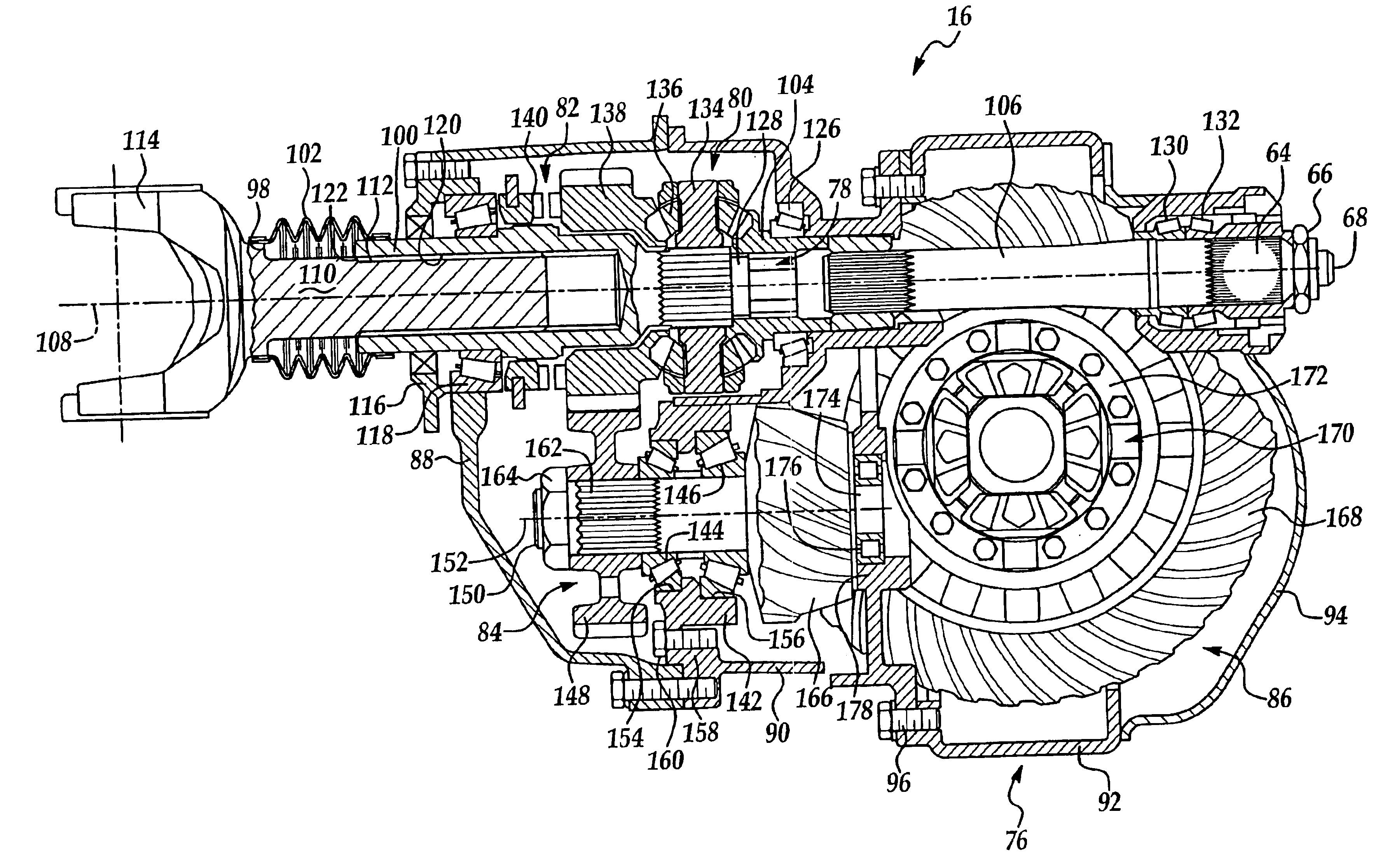
The present invention provides a tandem axle assembly for vehicles that eliminates the need for a splined slip connection in the driveshaft. This reduces the number of parts, cost, and weight of the driveshaft, as well as improves driveline balance. The assembly includes a first axle assembly with a wheel differential and a pinion shaft, and a second axle assembly with a wheel differential and an inter-axle differential. A power input shaft is coupled to the inter-axle differential and an output shaft is driven by the inter-axle differential. The assembly also includes an intermediate drive shaft with an output yoke and an input yoke driven by the output shaft. The one member of the power transmission shaft, the power input shaft, the output shaft, the output yoke, the input yoke, and the pinion shaft defines a bore, and the other member of the power transmission shaft, the power input shaft, the output shaft, the output yoke, the input yoke, and the pinion shaft extends into the bore with the one member axially movable relative to the another member.

Problems solved by technology

Forming the splined slip connection in the drive shaft assembly is disadvantageous.
The drive shaft requires two separate parts and is relatively costly and heavy.
Further the spline slip connection renders balancing of the driveshaft and driveline more difficult and increases runout of the driveshaft.

Method used


Image

  • Tandem axle power divider assembly with inboard slip driveshaft connection
  • Tandem axle power divider assembly with inboard slip driveshaft connection
  • Tandem axle power divider assembly with inboard slip driveshaft connection

Examples


Embodiment Construction

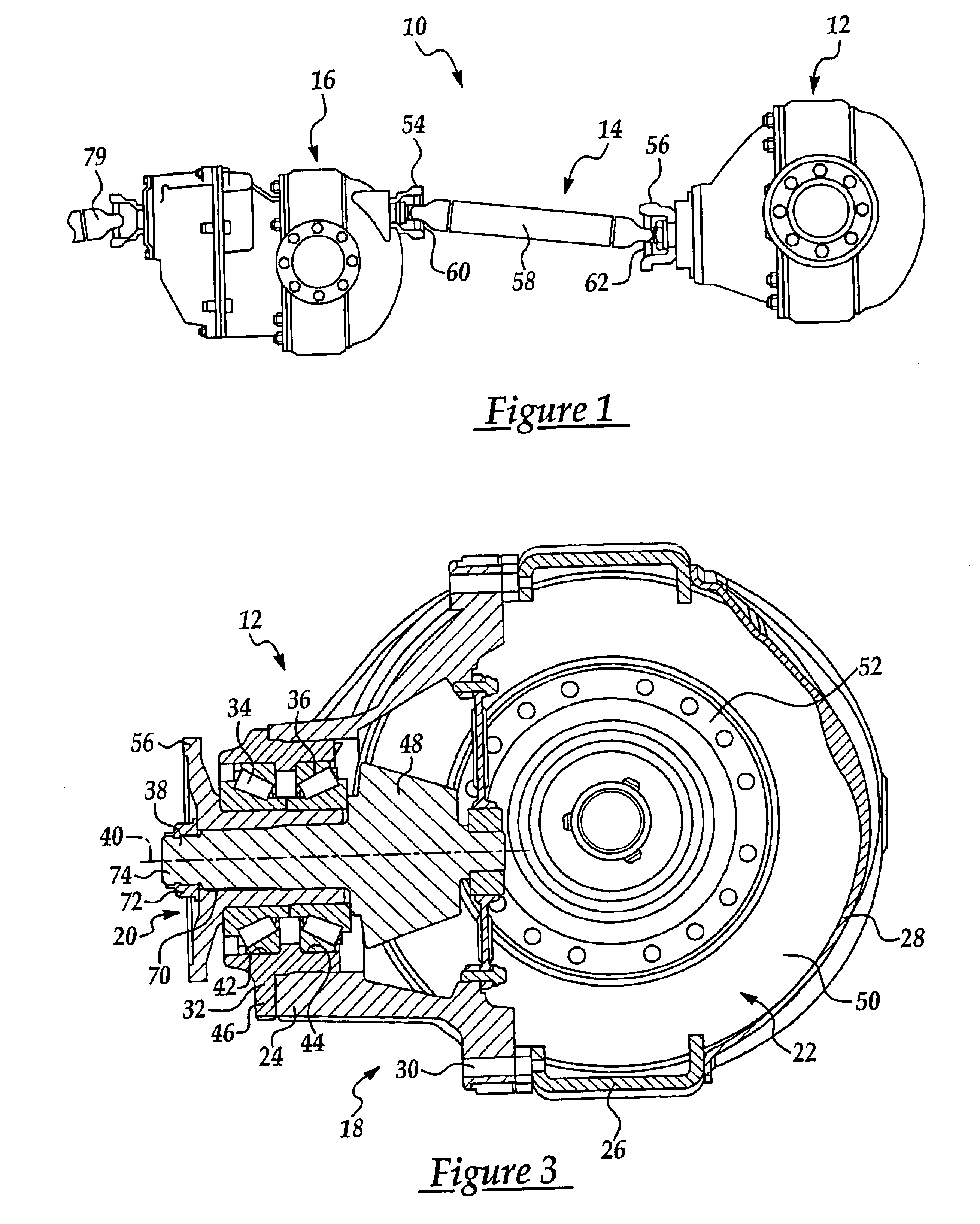
Referring now to the drawings wherein like reference numerals are used to identify identical components in the various views, FIG. 1 illustrates one embodiment of a tandem axle assembly 10 in accordance with the present invention. Axle assembly 10 is provided to support the frame (not shown) of a vehicle on a plurality of wheels (not shown). Assembly 10 is particularly adapted for use in medium and heavy trucks. It should be understood, however, that the present invention is not limited to use in heavy trucks and may be used in a wide variety of vehicles. Assembly 10 includes a rear axle assembly 12, an intermediate drive shaft assembly 14, and a forward axle assembly 16.

Rear axle assembly 12 is provided to drive wheels (not shown) supported on either side of assembly 12 on axle half shafts (not shown) extending from axle assembly 12. Referring to FIG. 3, assembly 12 may include a housing 18, a pinion shaft assembly 20 and a differential 22.

Housing 18 provides structural support for...


PUM


Abstract

A tandem axle assembly capable of accommodating variations in driveline length is provided. The tandem axle assembly includes forward and rear axle assemblies each having a wheel differential with the forward axle assembly further including an inter-axle differential for dividing power between the two wheel differentials. A male-female slip connection is formed between two members at one or more of the following intersections: the connection between a power input shaft driving the inter-axle differential and a power transmission shaft for transferring power from a vehicle driveshaft to the power input shaft; the connection between an output shaft driven by the inter-axle differential and an output yoke of an intermediate drive shaft assembly extending between the forward and rear axle assemblies; and the connection between an input yoke of the intermediate drive shaft assembly and a pinion shaft in the rear axle assembly drivingly coupled to the rear wheel differential.

Description

BACKGROUND OF THE INVENTION1. Field of the InventionThis invention relates to tandem axle assemblies and, in particular, to a tandem axle assembly designed to accommodate variations in length along the vehicle driveline during movement of a vehicle.2. Discussion of Related ArtA conventional tandem axle assembly includes forward and rear axle assemblies and an intermediate drive shaft assembly connecting the two axle assemblies. The forward and rear axle assemblies each include a pair of axle half shafts extending therefrom on which one or more wheels of a vehicle are mounted. Each of the forward and rear axle assemblies further include a differential that allows the vehicle wheels on each axle assembly to rotate at different speeds. Each of the differentials includes a pinion gear in mesh with a ring gear (which in turn drives a plurality of bevel gears to cause rotation of the axle half shafts). The pinion gears of the forward and rear axle assemblies are driven by an inter-axle di...

Claims


Application Information

Patent Timeline
Patent Type & Authority Patents(United States)
IPC IPC(8): B60K17/00B60K17/36
CPCB60K17/36F16H2048/426
Inventor HOLMAN, JAMES L.WILLFORD, GEORGE A.
Owner DANA AUTOMOTIVE SYST GRP LLC
Learn More