
Enhancing textured range images using a 2D editor

a 2d editor and textured range technology, applied in the field of computer graphics, can solve the problems of insufficient low-resolution models, difficult and time-consuming task of generating models with high-resolution geometry, and difficult to recreate the complexity and variety of geometric texture, etc., to achieve cost-effective, reduce labor, and simple effect of us

Inactive Publication Date: 2005-03-01
MITSUBISHI ELECTRIC RES LAB INC
View PDF1 Cites 11 Cited by
  • Summary
  • Abstract
  • Description
  • Claims
  • Application Information

AI Technical Summary

Benefits of technology

The invention provides a method for creating detailed 3D models from 2D photographs using a digital camera and a 2D image editor. The method involves generating textured range images from the 2D photographs and computing distances from these images to convert them to 3D models. The resulting 3D models are cost-effective, practical, and robust, with minimal labor and equipment requirements. The method can be used with a single image or multiple images and provides a powerful new design approach for generating and editing detailed 3D models.

Problems solved by technology

However, there are times when low-resolution models are insufficient.
However, generating models with high-resolution geometry is a difficult and time-consuming task.
It is often very hard to recreate the complexity and variety of geometric texture that occurs in nature.
High-resolution range scanners, such as Cyberware 3030, provide means for capturing existing geometry but high-resolution scanners are expensive and difficult to transport.
In addition, their spatial resolution is limited.
Hand-held range scanners are more portable, but they too are expensive for the casual user, and sacrifice both spatial and depth resolution for portability.
However, digital cameras do not provide explicit depth information.
However, that method can lead to holes in the model that must be addressed separately as described by Curless et al.

Method used


Image

  • Enhancing textured range images using a 2D editor
  • Enhancing textured range images using a 2D editor
  • Enhancing textured range images using a 2D editor

Examples


Embodiment Construction
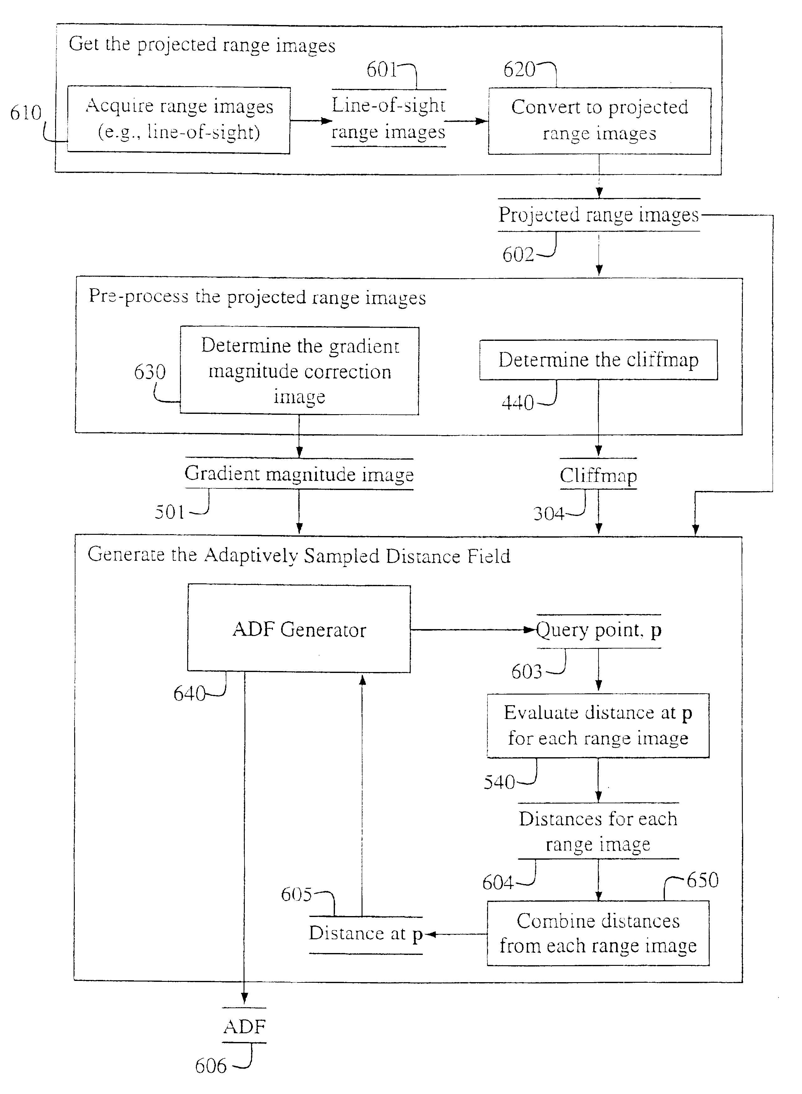
Projected Distances

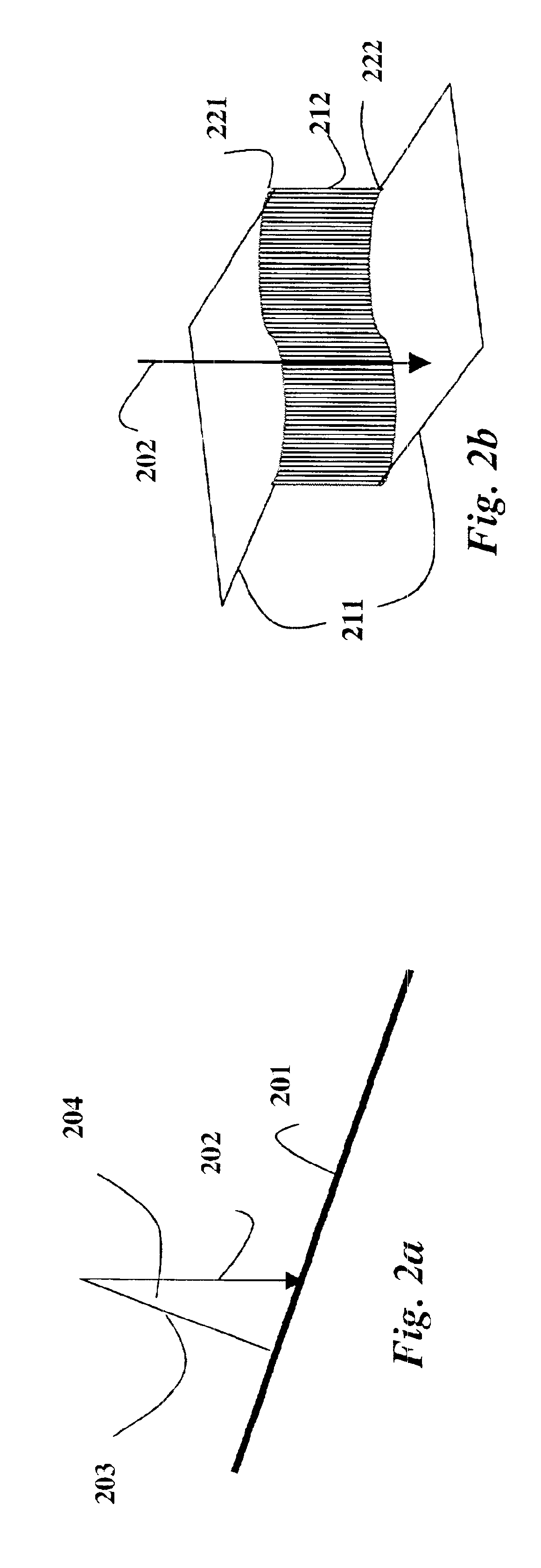
Two-dimensional (2D) range images provide a 2D grid of line-of-sight distances from a scanner to an object. A line-of-sight distance is measured along a viewing ray from the scanner to the object. In the following description, we assume that each distance value in the range image represents a perpendicular projected distance, where the distance is measured along a ray from the scanner to the object that is perpendicular to the plane of the scanner, also see U.S. Pat. No. 6,262,738 issued to Gibson, et al. on Jul. 17, 2001, “Method for estimating volumetric distance maps from 2D depth images,” incorporated herein by reference, for further details on this problem.

Scanning systems do not always provide projected distances but conversion to this form can be straightforward. As an example, laser striping systems “fan” a laser beam into a plane of laser light so that each scan line of the range image samples line-of-sight distances along rays radiating from the point la...


PUM


Abstract

A method edits a 3D model using 2D images. First, a projected range image is generated from a 3D model. The projected range image is edited using a 2D editor. A projected distance and a cliff distance from a plurality of 3D points to a 3D surface of the 3D model are determined using the edited projected range image. The projected distance and the cliff distance of each of the 3D points are combined to determine a distance from each 3D point to the 3D surface so that the distances forming a distance field of the edited 3D model.

Description

FIELD OF THE INVENTIONThe invention relates generally to computer graphics, and more particularly to generating and editing the geometry and texture of 3D models acquired from 2D images.BACKGROUND OF THE INVENTIONIn computer graphics, it is often desired to minimize the amount of geometry in a model of a scene or an object to enable efficient rendering of the model. Several effective approaches have been developed to add visual detail to low-resolution models during rendering, such as texture mapping and bump mapping, see Apodaca et al., “Advanced Renderman,” Morgan Kaufmann, ISBN 1558606181, 2000.However, there are times when low-resolution models are insufficient. For example, high-end production studios often require models with detailed explicit geometry for physical simulation, e.g., deformation and collision detection. In addition, these studios often employ sophisticated illumination that requires models with high-resolution geometry.Displacement mapping can be applied to the...

Claims


Application Information

Patent Timeline
Patent Type & Authority Patents(United States)
IPC IPC(8): G06T17/40G06T17/10
CPCG06T19/00G06T11/001G06T17/00G06T15/04G06T2200/08
Inventor PERRY, RONALD N.FRISKEN, SARAH F.
Owner MITSUBISHI ELECTRIC RES LAB INC
Learn More