
Stairclimber apparatus pedal mechanism

Inactive Publication Date: 2005-02-15
LIFE FITNESS LLC
View PDF28 Cites 70 Cited by
  • Summary
  • Abstract
  • Description
  • Claims
  • Application Information

AI Technical Summary

Benefits of technology

It is, therefore, a principal object and purpose of the present invention to provide an exercise apparatus that accurately and dynamically simulates stair climbing and is of a light weight and simple design.
It is another object and purpose of the present invention to provide a stair climbing exercise apparatus that simulates a natural stair climbing exercise and thereby promotes exercise efficiency.
It is an additional object and purpose of the present invention to provide a stair climbing exercise apparatus that is less stressful on the user's body ligaments than running, aerobic dancing or other aerobic exercises since it eliminates jarring of the body.
Both of the above embodiments of the invention can also include a data input means and a control means. The data input means permits the user to input control signals. The control means responds to the input control means to control the resistance member and apply a braking force to the pedal assemblies. The user can thus control the amount of resistance offered by the pedal assemblies and so can vary the degree of effort required to move the pedals. The invention thus can accommodate the individual needs and desires of different users.

Problems solved by technology

Some such apparatuses produce an unnatural heel to toe flexure that reduces exercise efficiency.
One disadvantage of this mechanism is that the angle in which the drive belts are connected to the pivot arms supporting the pedals varies as the pedals move up and down.
This results in variations in tension in the belt, torque loads and ultimately variations on the resistance applied to the pedals.
Also, such four-bar linkage pedal systems with frame plates tend to be noisy, have numerous pinch points, and substantially increase manufacturing and repair expense.
Moreover, due to the large number of pivot points in this type of linkage, the linkages frequently become loose and require frequent maintenance.

Method used


Image

  • Stairclimber apparatus pedal mechanism
  • Stairclimber apparatus pedal mechanism
  • Stairclimber apparatus pedal mechanism

Examples


Embodiment Construction

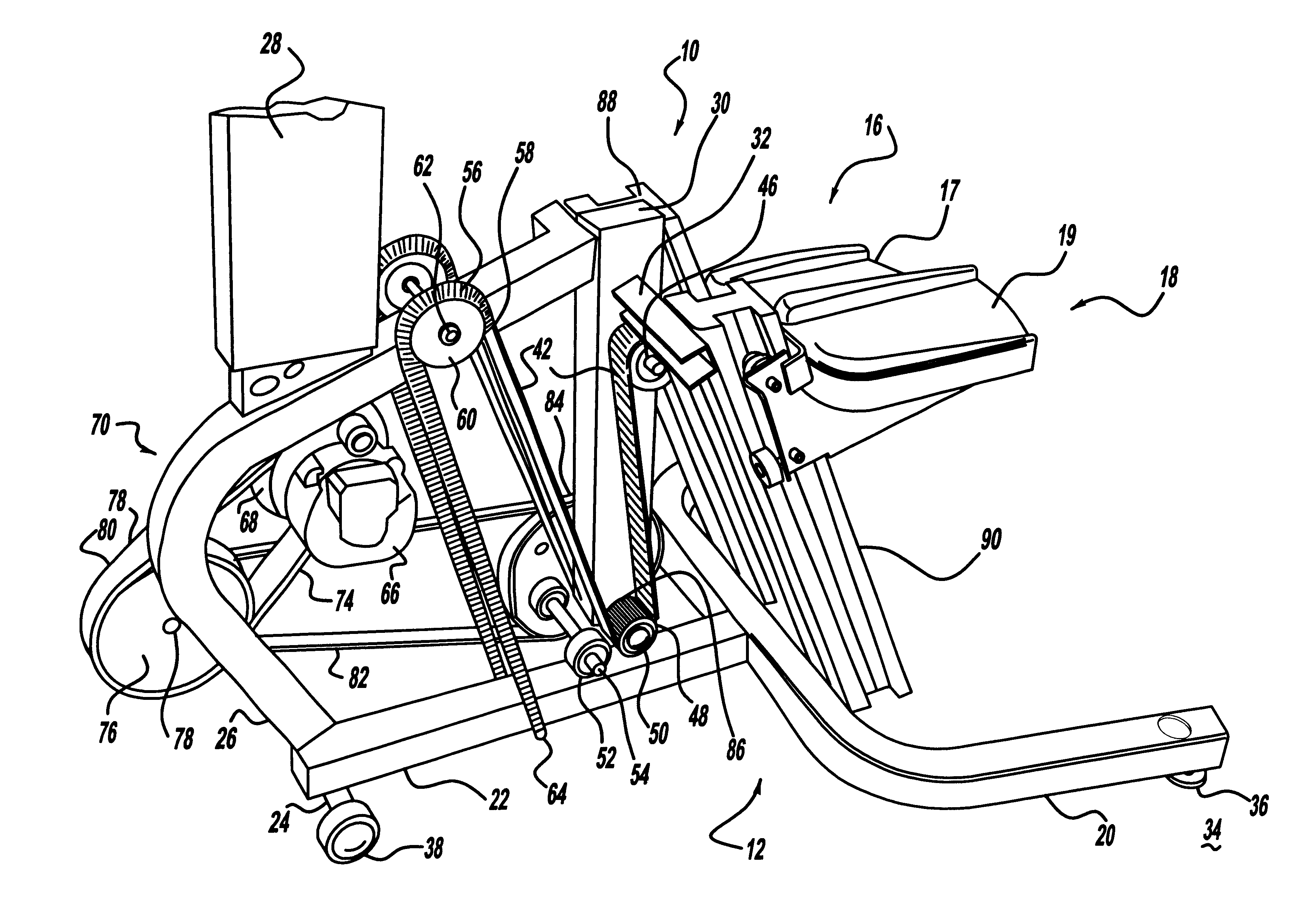
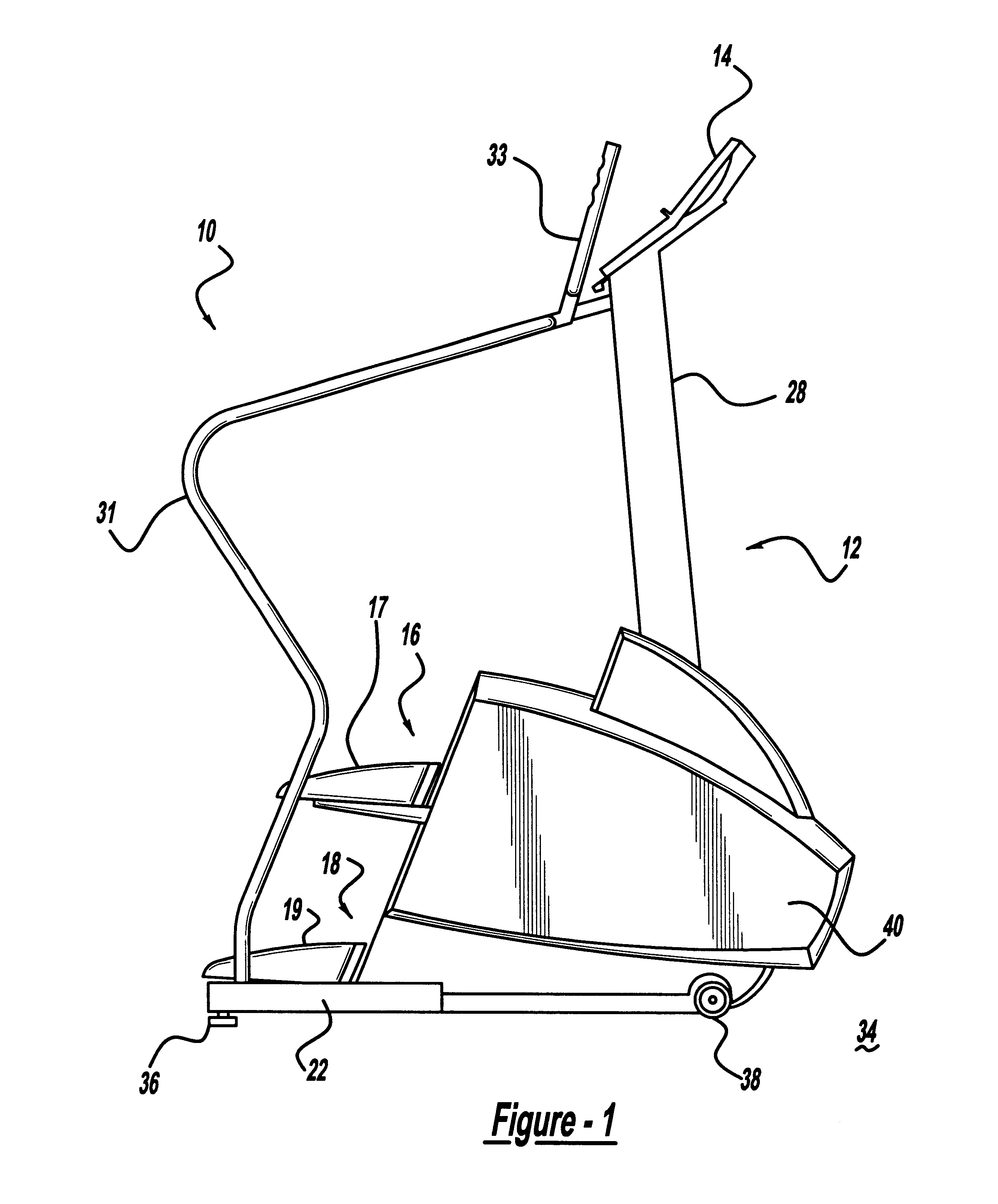
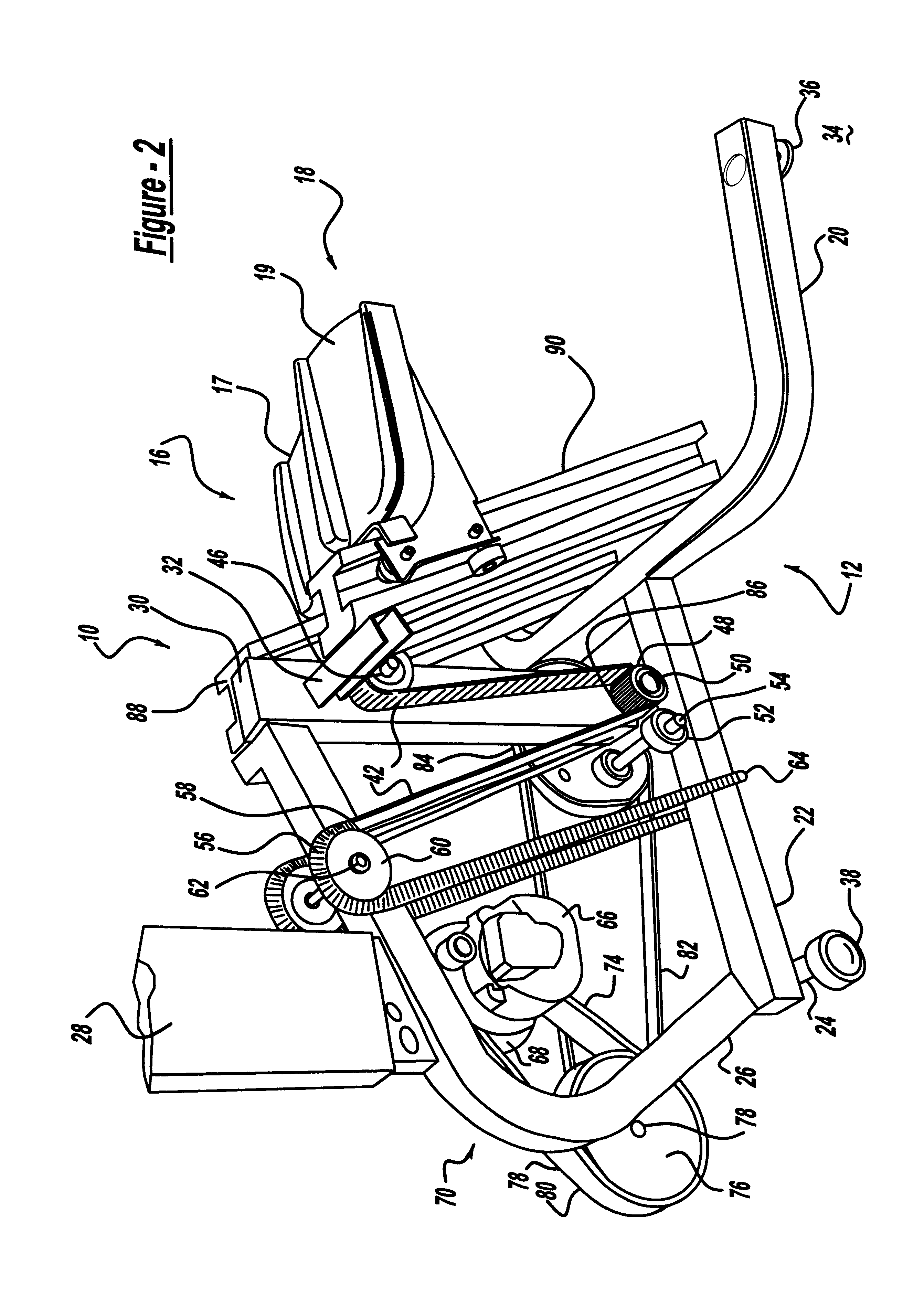
Referring to the drawings in detail, FIGS. 1 and 2 depict the preferred embodiment of a stair climbing-type exercise apparatus 10 that includes a tubular frame 12, a control panel 14, a right pedal assembly 16 including a pedal 17 and a left pedal assembly 18 including a pedal 19. The frame 12 acts as the supporting structure for the stair climbing-type exercise apparatus 10 and can be of any suitable construction. It should also be understood that a number of different frame structures can be used to support the elements of the apparatus 10 such as the frames shown in the existing stair climbers described above. In the illustrated preferred embodiment, the frame 12 includes a generally U-shaped support member 20, a longitudinal support member 22 secured to the U-shaped support member 20, a cross member 24 secured to the longitudinal support member 22, a generally curved support member 26 secured to the longitudinal support member 22, a first vertical support member 28 secured to th...


PUM


Abstract

A simulated stair climbing-type exercise apparatus is provided having a frame, a resistance member, a transmission, a drive belt, a right pedal assembly, a left pedal assembly and a track mounted to the frame to provide a user with a vertically reciprocating exercise movement. The right pedal assembly, operating independently of the left pedal assembly and having a set of rollers engaged with the track, oscillates between an upper position at rest and a lower position under the weight of the user. The left pedal assembly, operating independently of the right pedal assembly and having a set of rollers engaged with the track, oscillates between an upper position at rest and a lower position under the weight of the user. The pedal assemblies remain parallel to a support surface throughout their entire range of motion, as the pedal assemblies travel from their upper position to their lower position.

Description

FIELD OF THE INVENTIONThe present invention relates to exercise equipment and more particularly to exercise equipment which simulates aerobic stair climbing.BACKGROUND OF THE INVENTIONStair climbing is recognized as a particularly effective type of aerobic exercise, and as a result, exercise machines facilitating this type of exercise are popular for both home and health club use.There have been a variety of approaches taken in designing stair climbing apparatus, including the simulation of an actual staircase as illustrated in U.S. Pat. Nos. 3,497,215, 3,747,924, 4,687,195, 5,183,448, 5,263,909 5,299,993 and 5,336,143. Another approach has been to simulate the action of stair climbing by using a pair of reciprocating pedals.As exemplified by U.S. Pat. No. 5,135,447, reciprocating pedal machines include a pair of pedals which are adapted for vertical reciprocating motion to provide a user who is standing on the pedals with a simulated climbing exercise. The vertical reciprocating mo...

Claims


Application Information

Patent Timeline
IPC IPC(8): A63B23/04A63B21/005A63B24/00
CPCA63B22/205A63B21/0053A63B2225/30A63B2022/0038A63B24/00
Inventor ANDERSON, TIMOTHY T.DEKNOCK, BYRON T.TERMION, MARK C.
Owner LIFE FITNESS LLC
Learn More