
Adjustable shelf

a shelf and adjustable technology, applied in the field of storage and display items, can solve the problems of uneven surface, time-consuming and laborious projects, and not easy to move, and achieve the effect of not only unattractive, but not easy to stack items

Inactive Publication Date: 2005-02-15
DUBARRY SUZANNE
View PDF21 Cites 46 Cited by
  • Summary
  • Abstract
  • Description
  • Claims
  • Application Information

AI Technical Summary

Benefits of technology

The first leg and the second leg may include a foot positioned on a distal end thereof and opposite to the shelf portion, as a support on which the shelf may stand. The feet can be mounted to the legs by providing the first leg and the second leg each with a mounting tab positioned on a distal end thereof and opposite to the shelf portion. A mounting tab receiver is then positioned adjacent to the shelf portion on the leg opposite to the mounting tab. This also enables stacking of one shelf on the other by removing the feet and inserting the mounting tabs of one shelf in the mounting tab receivers of another shelf, thus releasably securing one to the other.

Problems solved by technology

Though the shelving is typically “movable” it is not easy to move.
This is a time consuming and labor-intensive project.
For the most part this is restricted to buying or building the shelf or bookcase at the desired width.
One of the problems is since there is an extension on a side the upper surface now has two levels, one for the base and one for the extension.
This uneven surface is not only unattractive, but does not lend itself well to stacking items.
Also, these devices do not provide for vertical or height adjustment.

Method used


Image

  • Adjustable shelf
  • Adjustable shelf
  • Adjustable shelf

Examples


Embodiment Construction

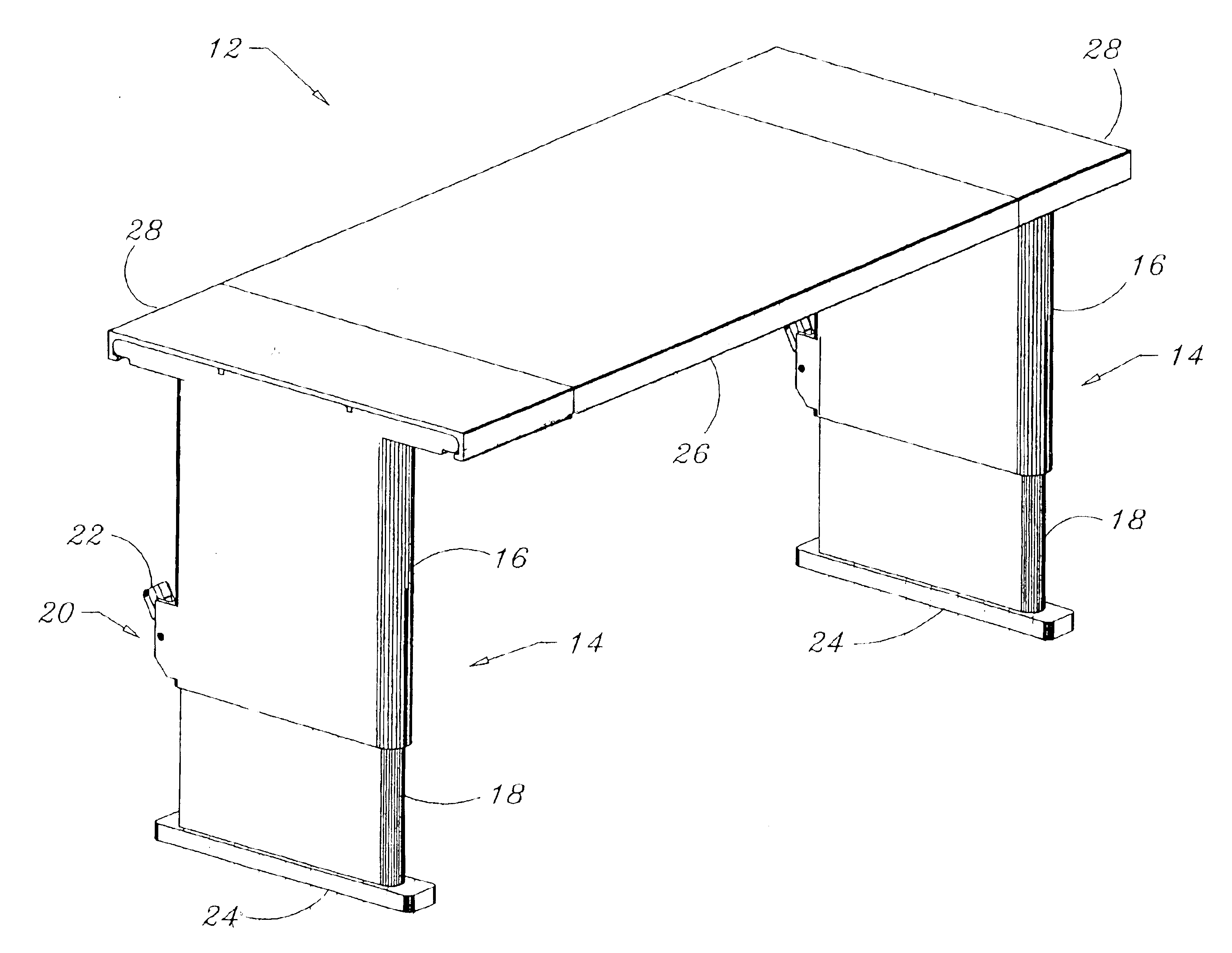
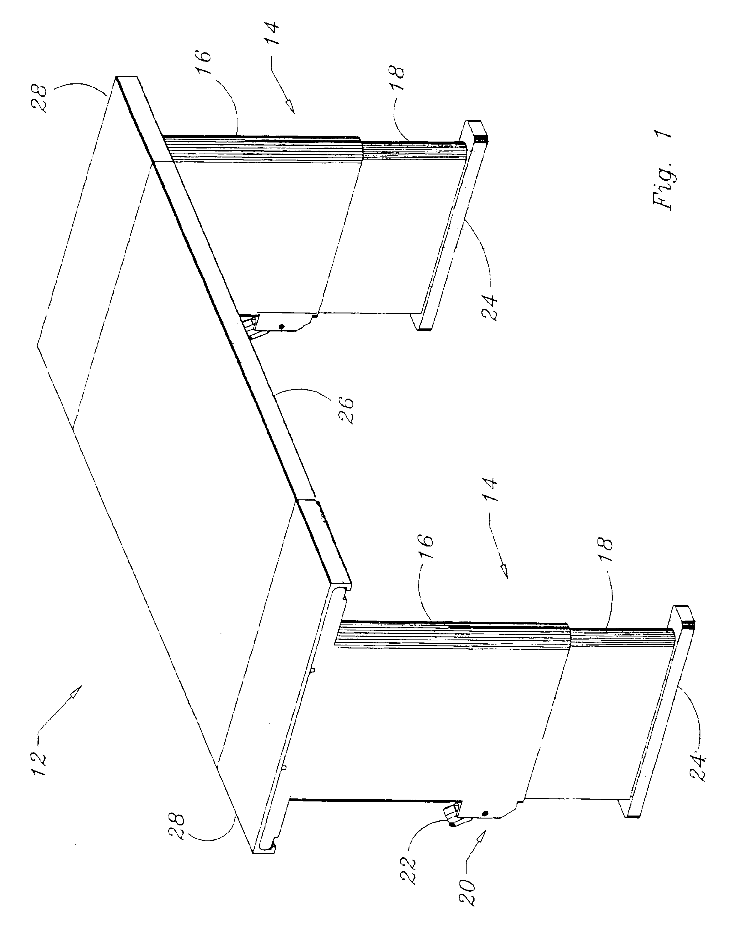
The present invention is an adjustable shelf that enables both vertical and horizontal adjustment. The fully assembled shelf 12 is shown in FIG. 1. This is a front, side, upper view that shows the preferred legs 14 which are comprised of a first portion 16 and a second portion 18. This two-part telescoping leg assembly allows for compact storage and an elegant appearance. A lock 20, shown here as a pawl 22, provides a set leg length that can be determined by the user. On the bottom of the second portion 18 of the leg 14, is positioned a foot 24. The foot 24 is optimally releasably mounted to the end of the second portion 18, but can be permanently fixed thereto. The advantage of the releasable mounting will be discussed later.

The upper end of the first portion 16 supports a planar surface including a shelf portion 26 and may include one or more end covers 28. The end covers 28 and the shelf portion 26 comprise the supportive surface on which items can be stored.

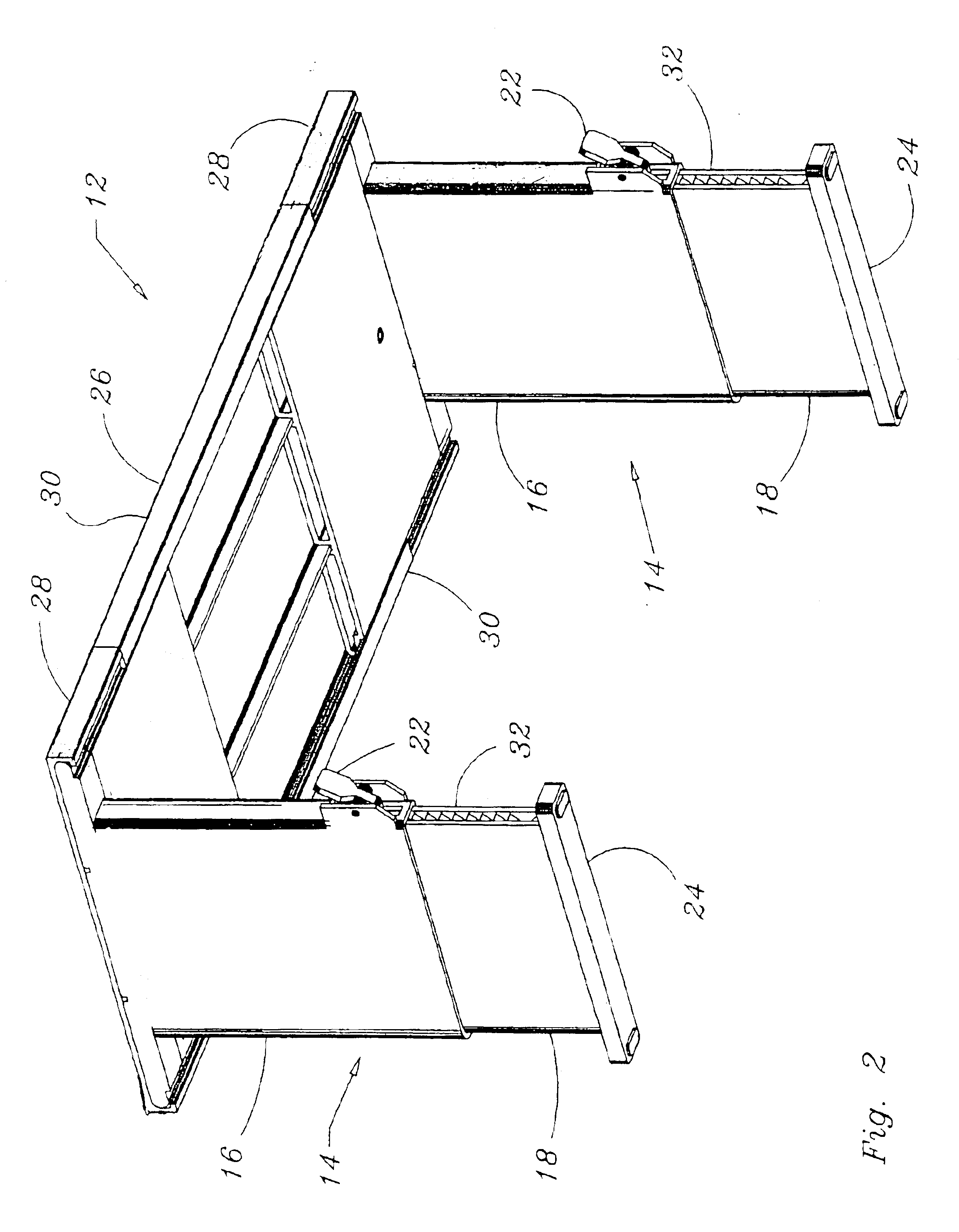
In FIG. 2 the “under ...


PUM


Abstract

A shelf stores items and provides for organized and attractive display with ease of item access. Conforming to a defined physical environment or variable storage space optimally requires the shelf to provide for both vertical and horizontal adjustment. Here this is accomplished by a pair of legs that are telescopic (to reduce size) and can be locked at a height (vertical adjustment) by use of a pawl, pin, screw or other fastener known in the art. The shelf includes a planar surface that is comprised of a shelf portion, which is supported on each distal end by a leg extension. The leg extensions are mounted to the upper area of the legs. The leg extensions are received by the shelf portion, being movably mounted thereto. This allows for horizontal (width) adjustment. An end cover can be used to provide a flat surface that is consistent with the upper surface of the shelf portion. Feet are added to provide a more solid footing, the feet being removable and providing a mounting tab at the end of the legs and a mounting tab receiver at the opposite end of the legs. This allows for multiple shelves to be securely mounted one on the other.

Description

FIELD OF THE INVENTIONThe present invention generally relates to storage and display items. More specifically, the present invention relates to shelving and even more specifically to adjustable shelving adapted to conform to a desired dimension.BACKGROUND OF THE INVENTIONAs our lifestyles become more and more complex, we desire devices that enable organization. This helps to bring our lives some sort of normality. Shelving products have evolved since the days of the uncovered “cup boards” in the late 18th century to the modern cabinets with decorator doors and movable shelving as seen today. Though the shelving is typically “movable” it is not easy to move. The shelves must be unloaded, some sort of stop or mounting on two or more corners must be removed, and repositioned, the shelf reinstalled and then the shelf can again be loaded. This is a time consuming and labor-intensive project. As such, it is usually only done when the shelving is installed and never moved again. Many peopl...

Claims


Application Information

Patent Timeline
IPC IPC(8): A47B1/08A47B23/00A47B1/00A47B9/14A47B9/06A47B9/00A47B45/00
CPCA47B1/08A47B9/06A47B45/00A47B23/00A47B9/14
Inventor DUBARRY, SUZANNEABELBECK, KEVIN G.
Owner DUBARRY SUZANNE
Learn More