
Network management equipment and communication path setting method

a network management equipment and communication path technology, applied in the field can solve the problems of increasing the burden of operators, troublesome and advanced operation of network management equipment, and facilitating the operation of setting the operation reference time relative to each nod

Inactive Publication Date: 2005-02-08
KK TOSHIBA
View PDF4 Cites 58 Cited by
  • Summary
  • Abstract
  • Description
  • Claims
  • Application Information

AI Technical Summary

Benefits of technology

[0013]By doing so, a station or a communication line with a failure can be recognized at a glance, and the human-machine interface can be improved.
[0037]Consequently, the operation for setting the operation reference time relative to each node can be facilitated.

Problems solved by technology

Therefore, the operation in the network management equipment becomes considerably troublesome and advanced, and the burden of operators is getting large.
As described above, in recent transmission systems, the operation in the network management equipment becomes troublesome and advanced, and the provision of any countermeasure is demanded.

Method used


Image

  • Network management equipment and communication path setting method
  • Network management equipment and communication path setting method
  • Network management equipment and communication path setting method

Examples


Embodiment Construction

S Control window;

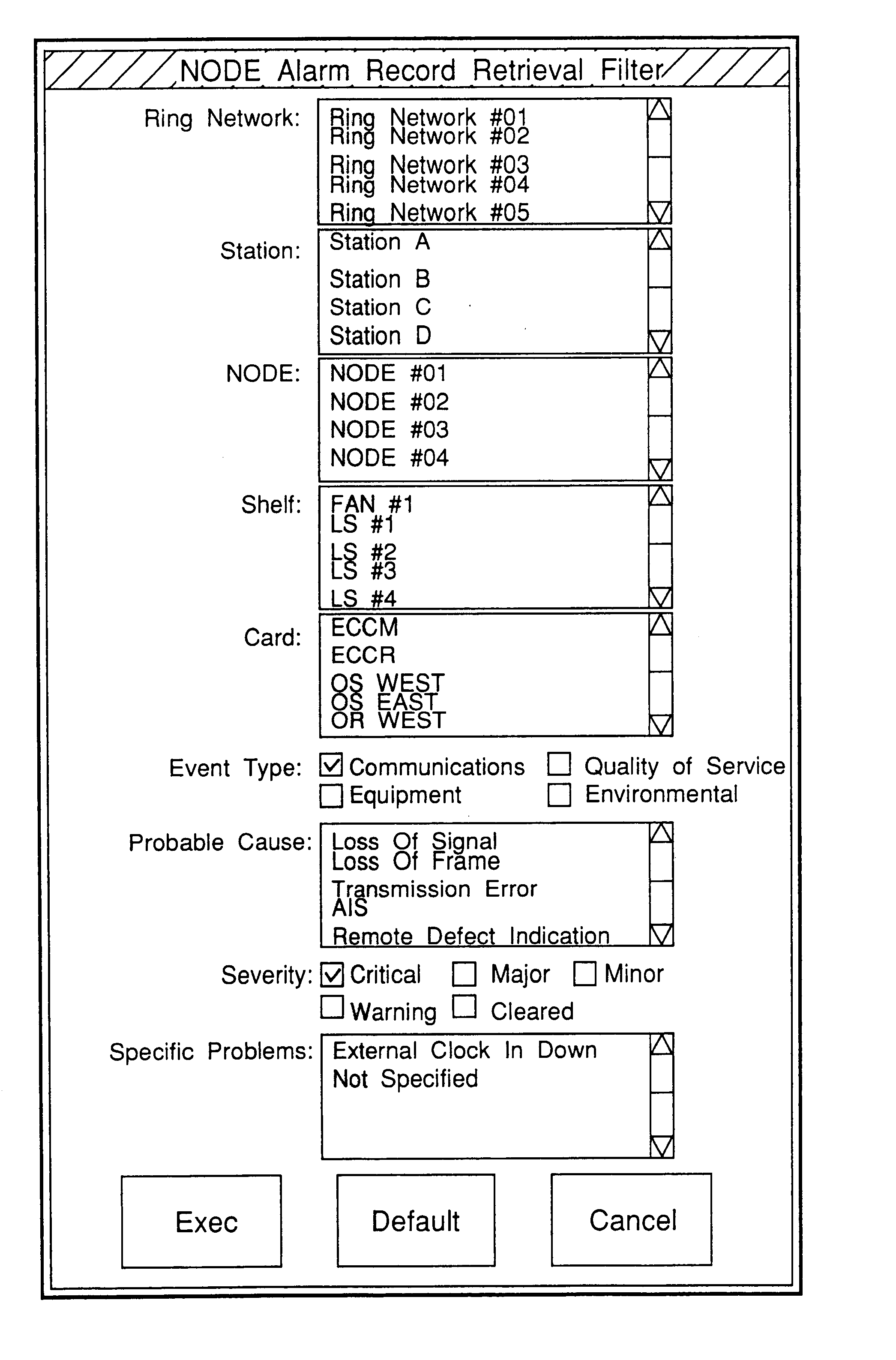
[0126]FIG. 87 is a view showing a Protection Section Selection window;

[0127]FIG. 88 is a view showing an APS Setting window;

[0128]FIG. 89 is a view showing a Protection Switching Control window;

[0129]FIG. 90 is a view showing a Switching Section Selection window;

[0130]FIG. 91 is a view showing a Path Configuration Control window;

[0131]FIG. 92 is a view showing a Path Configuration window;

[0132]FIG. 93 is a view showing a Path Update window;

[0133]FIG. 94 is a view showing a Node Information window;

[0134]FIG. 95 is a view showing a Path Name Update window;

[0135]FIG. 96 is a view showing a Path Name Input window;

[0136]FIG. 97 is a view showing a Diagnostics window;

[0137]FIG. 98 is a view showing an Irregular GTP Deletion window;

[0138]FIG. 99 is a view showing a Protection Status Information window;

[0139]FIG. 100 is a view showing a display example of a Path Configuration Control window;

[0140]FIG. 101 is a view showing a Ring Map Administrative Control window;

[0141]FIG....


PUM


Abstract

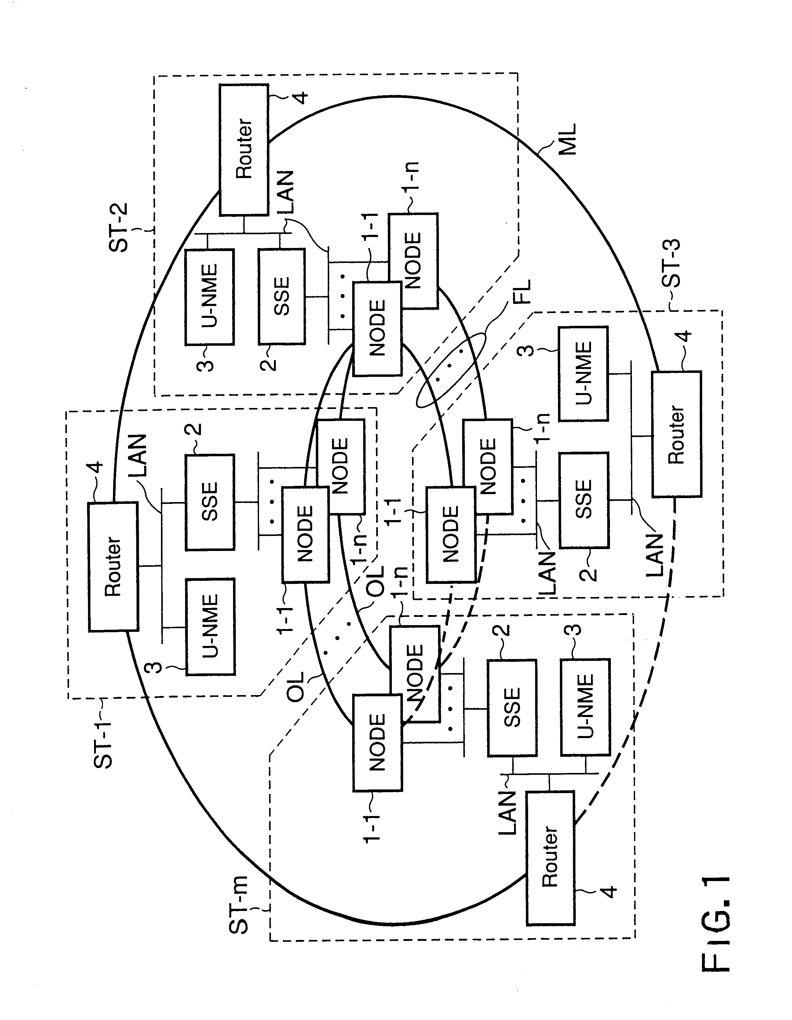
A graphics map of an area in which a system is set is displayed on a screen of a display unit, and minimized stations and line connecting between the stations are displayed on the map. Display colors of the station icon and the line icon are changed in accordance with presence / absence of a failure. When each station icon is clicked, a window showing a list of NODEs belonging to that station is opened, and a NODE having a failure and a NODE having no failure are also distinguished from each other by changing the display colors in this window.

Description

CROSS REFERENCE TO RELATED APPLICATIONS[0002]This is a Continuation Application of PCT Application No. PCT / JP01 / 01271, filed Feb. 21, 2001, which was not published under PCT Article 21(2) in English.[0003]This application is based upon and claims the benefit of priority from the prior Japanese Patent Application No. 2000-043199, filed Feb. 21, 2000, the entire contents of which are incorporated herein by reference.BACKGROUND OF THE INVENTION[0004]1. Field of the Invention[0005]The present invention relates to a network management equipment for managing a system in an information transmission system, e.g., an information transmission system such as an optical submarine cable system.[0006]2. Description of the Related Art[0007]In general, a node for transmitting communication data and a network management equipment for providing OAM (Operations, Administration and Maintenance) services to a communication network are provided to a transmission system.[0008]Meanwhile, in recent years, t...

Claims


Application Information

Patent Timeline
IPC IPC(8): H04L12/26H04L12/24H04L12/70
CPCH04L12/2602H04L41/0681H04L41/0853H04L41/22H04L45/28H04L45/22H04L43/00H04L43/0847H04L43/16
Inventor UENO, MICHIKONAKAO, TOORUIWASAKI, HIDETOSHIARIGA, YASUSHIYAMAMOTO, YOUKONAKAGAWA, HAKARUYAMAGUCHI, KIYOSHIAKIMOTO, TATSUKONAGANO, MASAAKIIZAWA, SHINICHIWATANABE, SHINSUKE
Owner KK TOSHIBA
Learn More