
Tent structure

a tent and structure technology, applied in the field of tents, can solve the problems of increasing the weight of the tent, hardly minimizing, and insufficient structure strength, and achieve the effects of facilitating draining, facilitating operation, and improving flexibility

Inactive Publication Date: 2005-02-01
TSAI TONY
View PDF19 Cites 52 Cited by
  • Summary
  • Abstract
  • Description
  • Claims
  • Application Information

AI Technical Summary

Benefits of technology

It is the primary object of the present invention to provide a tent structure, which is easy to operate and has a better flexibility to form an arcuate top to facilitate draining rain and to minimize wind.
It is another object of the present invention to provide a tent structure, which provides a support on the retractable rod to enhance the structure of the tent.
It is a further object of the present invention to provide a tent structure, which is easy to expand and to collapse, and has a compact size for ease in storing and carrying.

Problems solved by technology

However, this structure is not strong enough and will be bent inwardly at the top center portion, which collects water when it rains and gains more weight to the tent.
However, this design also comprises some shortcomings, such as:1. The top is not in arcuate shape, which cannot facilitate draining water and can hardly minimize wind.2. The retractable rod set has no support.3. It's not easy to collapse and to expand, and also provides no convenience in storage and carrying.

Method used


Image

  • Tent structure
  • Tent structure
  • Tent structure

Examples


Embodiment Construction

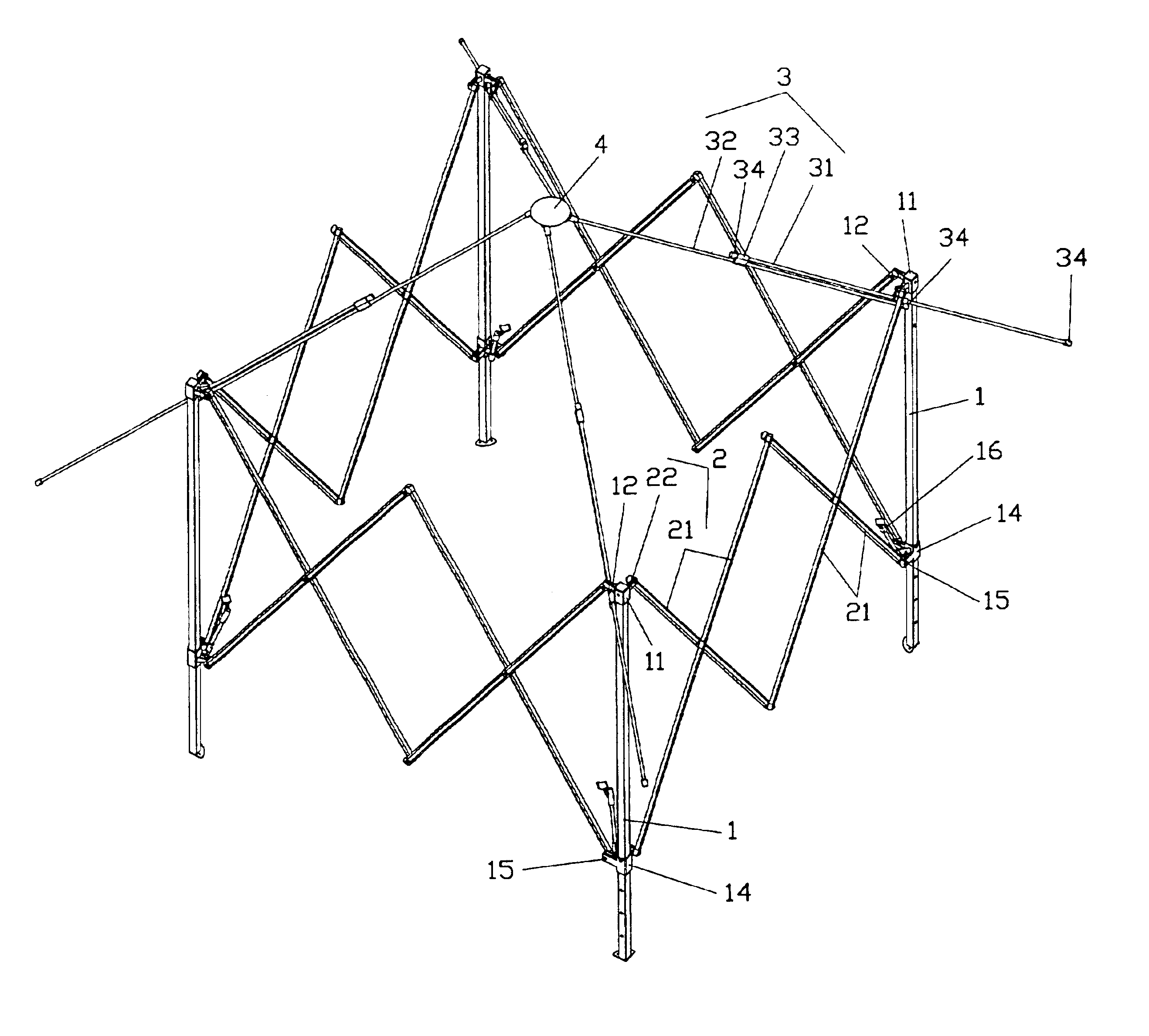
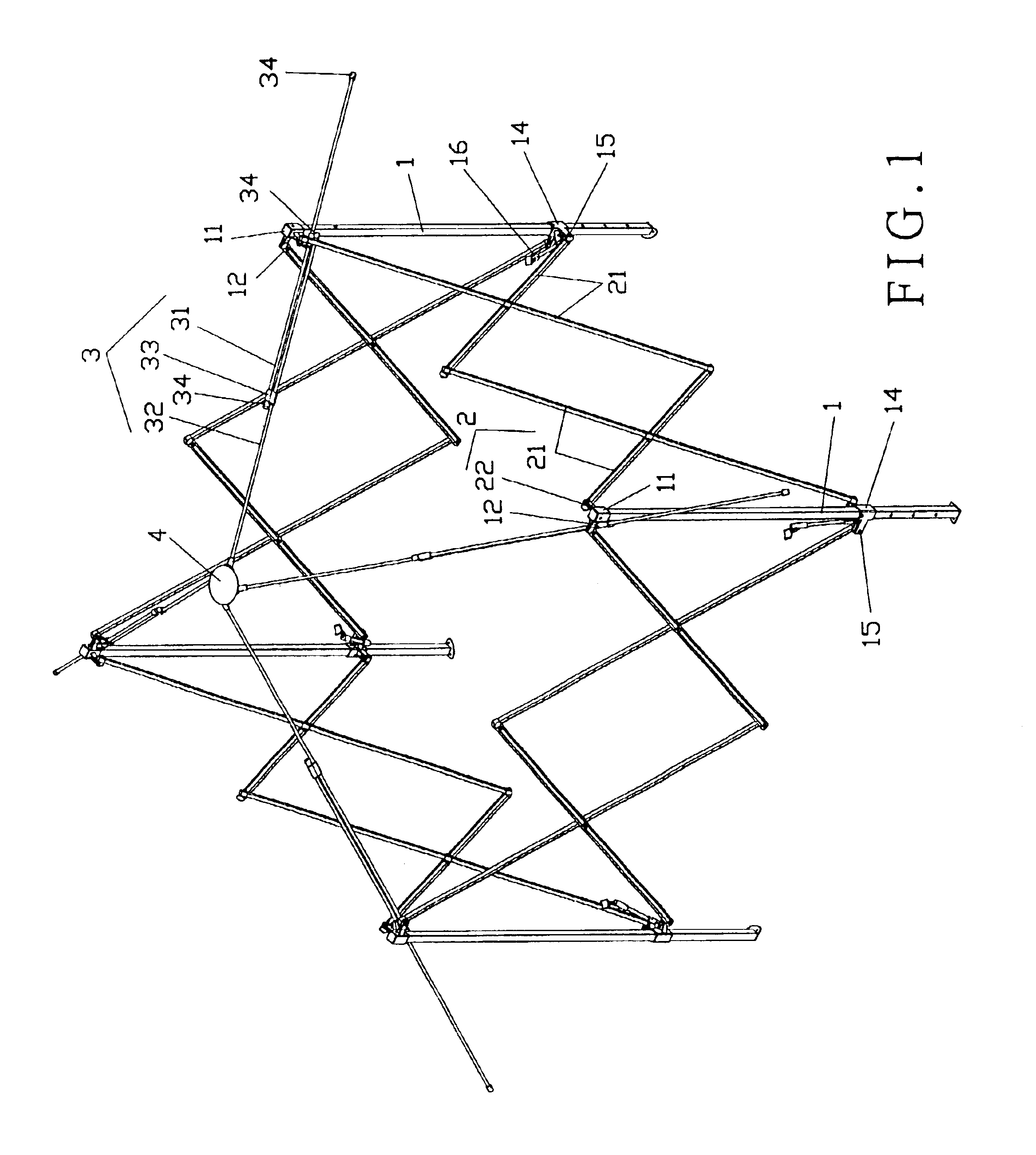
Reference is now made to FIG. 1 of the tent structure of the present invention, which is generally composed of four posts 1, four scissor-like linking rod sets 2, four retractable rod sets 3, and a connector 4.

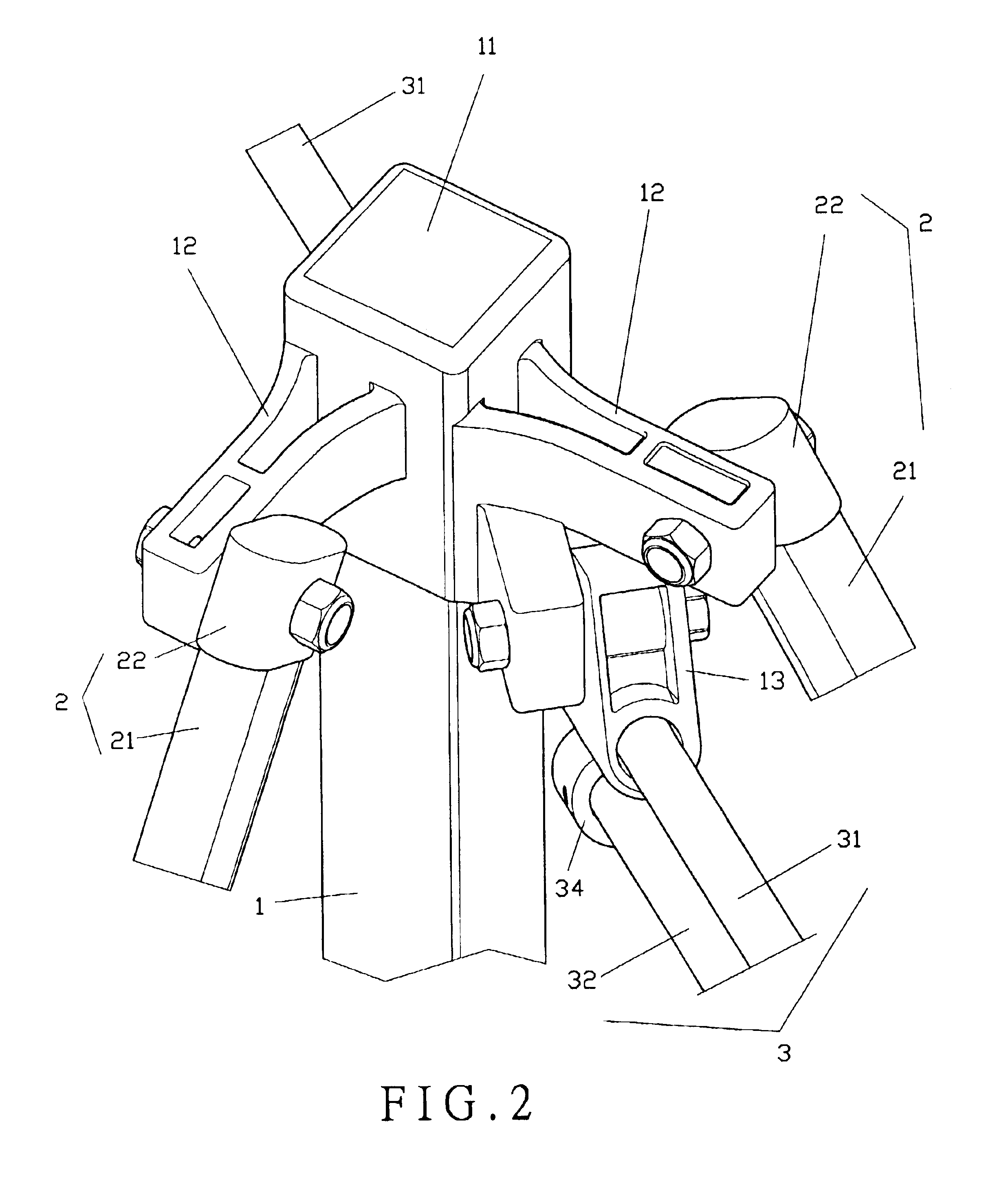
The four posts 1 stand on four corners of the tent, as shown in FIG. 2. Each post 1 has a fixture 11 on the top thereof with a pair of connecting lugs 12 on two sides next to each other. A sleeve 13 is formed between the connecting lugs 12. As shown in FIG. 3, a sliding seat 14 sleeves on the post 1 with a pair of connecting lugs 15 on two sides next to each other corresponding to the connecting lugs 12 of the fixture 11. A supporting rod 16 is upwardly provided between the two connecting lugs 15 with a supporting arm 161 at the top end thereof.

The four scissor-like linking rod sets 2 are secured between the four posts 1, respectively. Each scissor-like linking rod set 2 comprises four rods 21, and every two rods 21 are connected at the center portion thereof to form an X-shap...


PUM


Abstract

A tent structure includes four posts, four scissor-like linking rod sets, four retractable rod sets and a connector. The four posts are placed on four corners of the tent to form a square structure. Each post comprises a fixture at the top portion with a sleeve thereon at an upper portion and a sliding seat thereon at a lower portion. The sliding seat comprises a supporting rod. The four scissor-like linking rod sets are secured between the posts, respectively. One end of each retractable rod set is inserted through the sleeve of each post and the other end of the retractable rod set is pivoted to the connector, thus when the posts are expanded outwardly, the scissor-like linking rod sets are also expanded to form an arcuate tent.

Description

FIELD OF THE INVENTIONThis invention relates to a tent, and more particularly, to a tent with extending flexibility and sustainability.BACKGROUND OF THE INVENTIONThere are various tents on the market, most of which are of the enclosed type, which is to cover a structure with a canopy with one side left open for air flow, and the center top portion is supported by four pillars on four corners to raise upwardly at the connecting portion. However, this structure is not strong enough and will be bent inwardly at the top center portion, which collects water when it rains and gains more weight to the tent.In view of the above shortcoming, this inventor had invented a new design in U.S. Pat. No. 5,638,853, which has the four pillars standing straight, and each pillar has a vertical retractable scissor-like rod thereon, which is connected with each other to form a square shape structure. Each pillar comprises a fixture and a sliding seat adapted to connect with the free end of the scissor-l...

Claims


Application Information

Patent Timeline
Patent Type & Authority Patents(United States)
IPC IPC(8): E04H15/34E04H15/50
CPCE04H15/50
Inventor TSAI, TONY
Owner TSAI TONY
Learn More