
Systems and methods for executing functions for objects based on the movement of an input device

a technology of input devices and functions, applied in the field of data processing systems, can solve the problems of poor user interaction, inconvenient arrangement, and more complex devices, and achieve the effect of avoiding user uncertainty and increasing the degree of freedom of movemen

Inactive Publication Date: 2005-01-25
SAP AG
View PDF7 Cites 20 Cited by
  • Summary
  • Abstract
  • Description
  • Claims
  • Application Information

AI Technical Summary

Benefits of technology

The present invention provides a method for interacting with a computer system using an input device, such as a mouse or a data input glove. The method involves identifying a movement pattern in the user's movements and associating it with a function. This allows the user to perform intuitive movements without needing to learn specific movements. The method can be used in different environments and can be personalized for each user. The invention also provides a way to execute multiple functions with a single movement of the input device. The technical effects of the invention include increased accessibility for handicapped individuals, improved user experience, and enhanced security.

Problems solved by technology

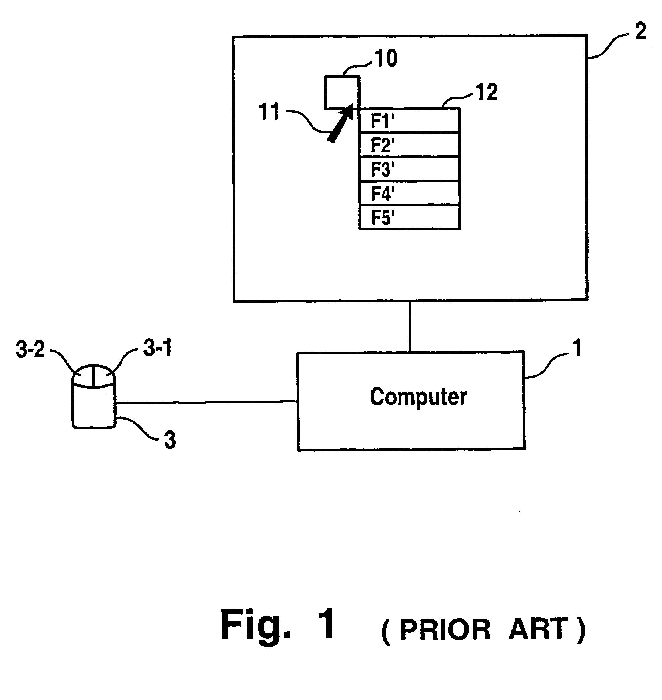
However, such technological developments of mouse-like devices makes these devices more complex.
For some users, however, this arrangement might be inconvenient compared to traditional mouse-like devices.
However, for pen-like devices, a technical problem arises in that there's nothing like a second (e.g., right) or third mouse button to provide an input signal that is different from the first (e.g., left) button to show, for example, a context menu for a displayed object Therefore, large menus that offer all possible functions for all possible types of objects have to be displayed simultaneously on a very small-sized display.
This requires, for example, to represent the functions by tiny icons or to have multi-layered menus that imply poor user interaction.
This creates the problem of limited interaction functionality, especially for graphical user interfaces.

Method used


Image

  • Systems and methods for executing functions for objects based on the movement of an input device
  • Systems and methods for executing functions for objects based on the movement of an input device
  • Systems and methods for executing functions for objects based on the movement of an input device

Examples


embodiment 300

FIG. 7 illustrates two alternative solutions for object correlation, consistent with embodiments of the present invention. Embodiment 300 illustrated in FIG. 7 provides a first solution for correlating matching movement pattern 221 with object 125. In this embodiment, a virtual grid 310 is permanently associated with object 125. Grid 310 describes a specific segmentation of the display area around object 125. For example, grid 310 can be implemented as an invisible structure in a portion of memory 190 (not shown) that stores data for display. Grid 310 is preferably centered at object center 315, but it is sufficient that a designated coordinate of grid 310 (e.g., the center) is in a defined relationship to a designated coordinate of object 125. The size of grid 310 is automatically adjusted to the size of the graphical representation of object 125. For example, this is achieved by varying the width and height of grid 310 until a predefined ratio of the grid size compared to the obje...

embodiment 350

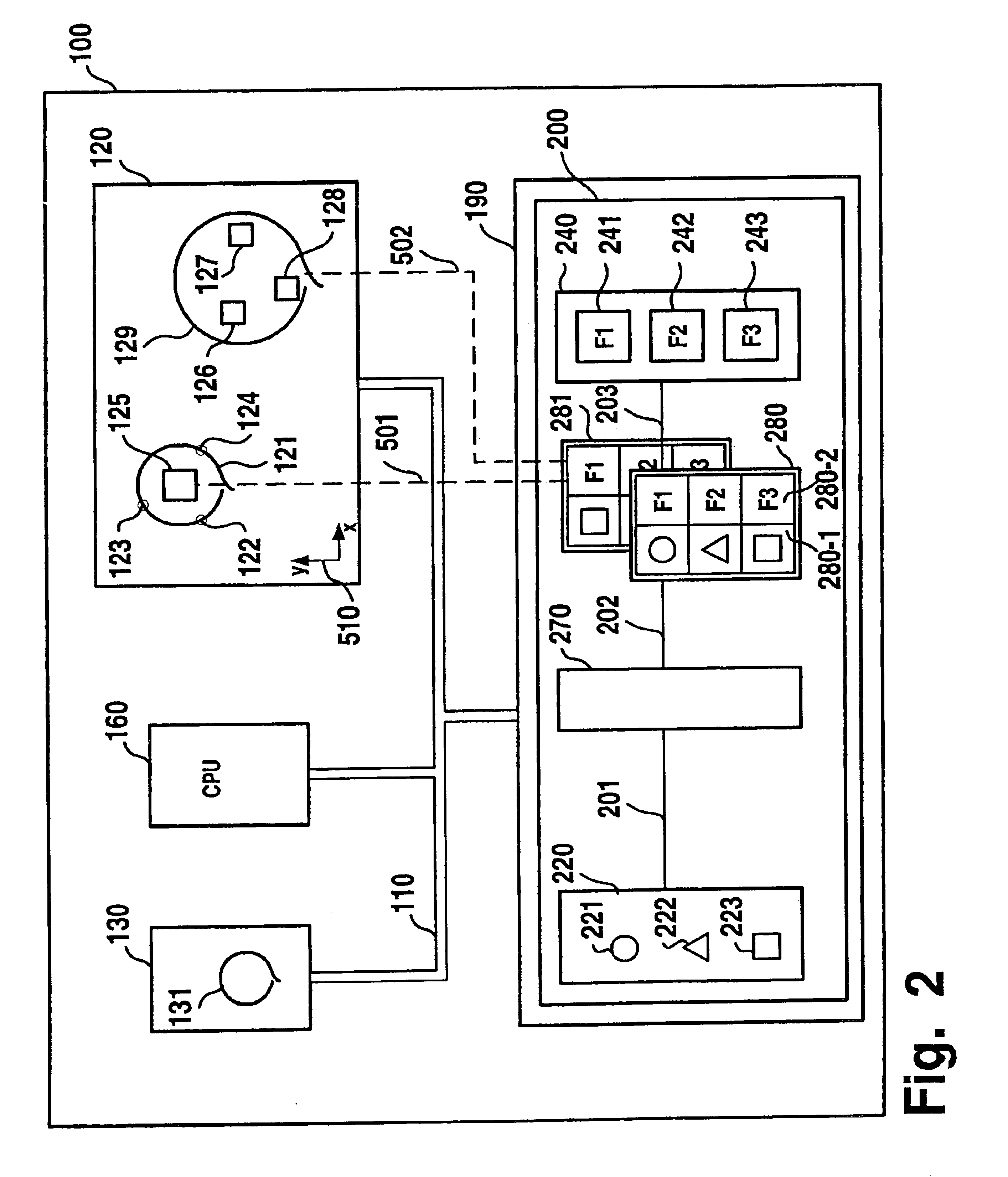
Embodiment 350 illustrated in FIG. 7 provides a second solution for correlating matching movement pattern 221 with a plurality of objects 126-128. In this embodiment, for example, the operating system of system 100 (not shown), continuously transfers further cursor movement data 129 to pattern identifier 270 (cf. FIG. 2). Once pattern identifier 270 identifies matching movement pattern 221, CPP 200 determines object selection area 360 based on further cursor movement 129 and, for example, the tolerances that are stored with matching movement pattern 221 in plurality 220. CPP 200 then identifies object centers 356-358 as lying inside area 360 and, therefore, correlates matching movement pattern 221 with objects 126-128, respectively.

FIG. 8 illustrates a further embodiment of the present invention that includes a personal digital assistant (PDA) 100-1 with a display device 120-1 and a stylus input device 130-1. The PDA, for example, serves as a front-end computer to remotely launch ap...


PUM


Abstract

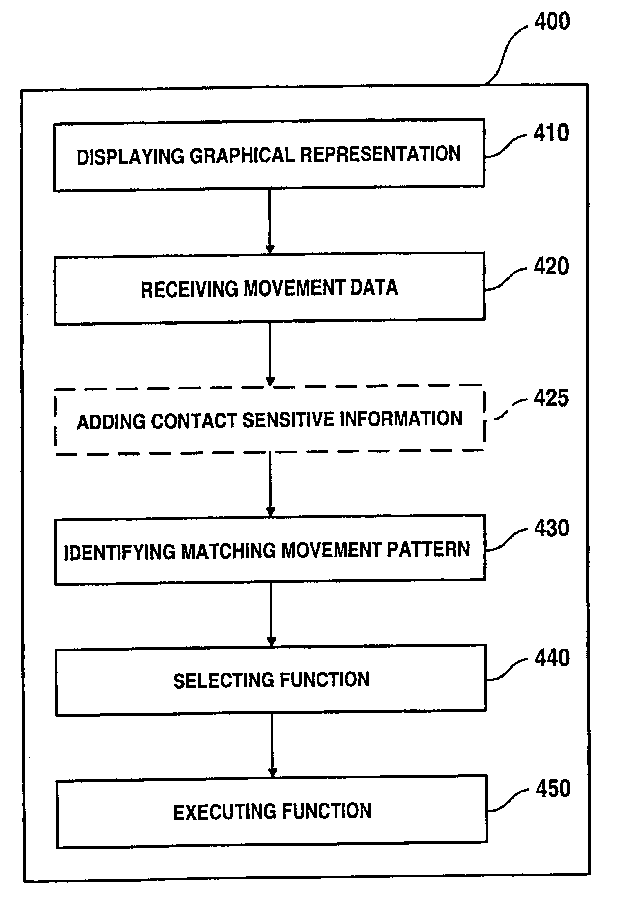
Methods, computer program products and systems are provided for executing a function of a data processing computer system. The function may relate to an object. The method may be performed by: displaying a graphical representation of an object on a display device; receiving movement data from an input device, identifying a matching movement pattern that matches the cursor movement, which corresponds to the movement data; selecting a function that relates to the matching movement pattern and the object; and executing the function for the object. The identifying step can be performed by measuring the cursor movement as changes of the cursor coordinates occur. The result may then be compared to a plurality of predefined reference movement patterns. One movement pattern may be selected out of the plurality of reference movement patterns as the matching movement pattern for the object.

Description

BACKGROUND OF THE INVENTIONI. Field of the InventionThe present invention generally relates to data processing systems. More particularly, the invention relates to systems and methods for improving user interaction with data processing systems, including data processing systems implemented with computers.II. Background InformationTypically, the interaction of a human user with a data processing system (such as a computer) occurs through a graphical user interface (GUI). A GUI may include a display device (such as a monitor) and an input device (such as a mouse). The user points at graphical objects that are displayed on the display device with a moving cursor that can be controlled by the user through the movement of the input device. To facilitate user interaction through graphical interfaces, buttons or a wheel for scrolling may be added to the input device. Such additional hardware allows the user to not only point at displayed objects, but also to execute designated functions in...

Claims


Application Information

Patent Timeline
Patent Type & Authority Patents(United States)
IPC IPC(8): G06F3/033G06F3/0488G06F3/041
CPCG06F3/04883
Inventor ROJEWSKI, ERWIN
Owner SAP AG
Learn More