
Charge balancing systems and methods

a technology of charge balancing and charging system, applied in the direction of secondary cell servicing/maintenance, electrochemical generator, transportation and packaging, etc., can solve the problems of adversely affecting the life of the battery, the charge of the individual the failure of other batteries in the string, so as to achieve the effect of easy scaling

Inactive Publication Date: 2005-01-11
ALPHA TECHNOLOGIES SERVICES INC
View PDF21 Cites 146 Cited by
  • Summary
  • Abstract
  • Description
  • Claims
  • Application Information

AI Technical Summary

Benefits of technology

The present invention may easily be scaled to accommodate any number of series connected batteries. The invention may further be implemented as a method of equalizing voltages across a plurality of series connected batteries. The present invention may additionally be implemented as part of a charging system for charging a plurality of series-connected batteries.

Problems solved by technology

In practice, however, variations in individual batteries and charging conditions may cause an imbalance in the charge on individual batteries in the string.
Continued imbalance of one battery in the string adversely impacts the life of that battery.
In addition, when one battery fails, other batteries in the string tend to fail.

Method used


Image

  • Charge balancing systems and methods
  • Charge balancing systems and methods
  • Charge balancing systems and methods

Examples


Embodiment Construction

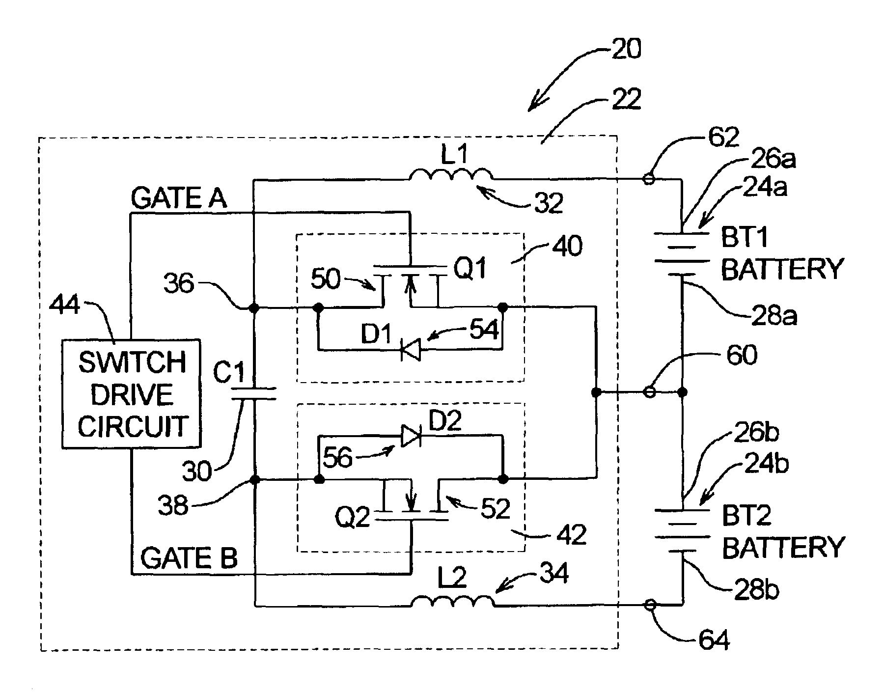
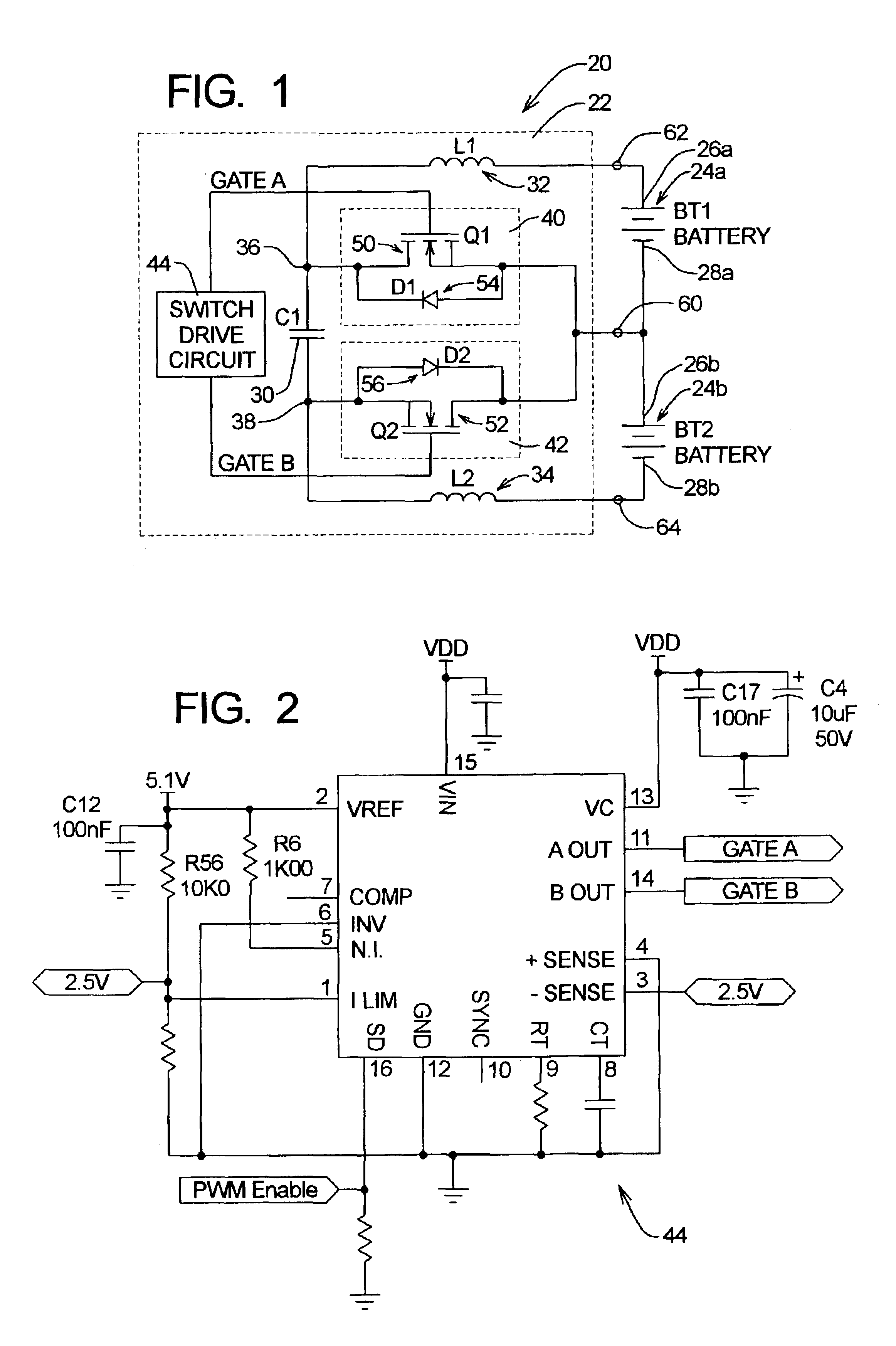
Referring initially to FIG. 1, depicted at 20 therein is a charge balancing system constructed in accordance with, and embodying, the principles of the present invention. The exemplary charge balancing system 20 comprises a charge balancing circuit 22 configured to balance the charge on each of a plurality of storage elements 24 connected in series. The storage elements 24 are depicted as, and will be referred to herein as, batteries. The principles of the present invention may, however, be applied to other devices for storing electrical energy, including electrostatic devices such as capacitors or super-capacitors.

The exemplary system 20 employs first and second batteries 24a and 24b, but the exemplary circuit 22 may be applied to strings of batteries comprising more than two batteries as will be described in further detail below. In the following discussion, letter suffixes are used to distinguish among the storage elements in a string of series-connected storage elements.

As is co...


PUM


Abstract

A system for equalizing the voltages across first and second batteries coupled in series at a common terminal comprising a capacitive storage element, first and second inductive storage elements, first and second switch circuits, and a control unit. The capacitive storage element is coupled to first and second nodes. The first inductive storage element is coupled between the first node and the first battery. The second inductive storage element is coupled between the second node and the second battery. The first switch circuit is coupled between the first node and the common terminal. The second switch circuit is coupled between the second node and the common terminal. The control circuit operates the first and second switch circuits to control current flow to the first and second batteries.

Description

BACKGROUND OF THE INVENTIONMany electrical devices and systems operate at least partly on electrical power stored in storage elements. Storage elements are conventionally manufactured to supply direct-current power at a predetermined voltage level. If the electrical device or system to be powered requires a higher voltage level, the higher voltage level 's obtained by connecting a plurality of storage elements in series.Currently, the most prevalent type of storage element is a battery. A battery is an electrochemical cell that can be charged electrically to store electric power and provide electric power when needed at a later time. The present invention is of particular significance when applied to two or more series connected batteries, and that application of the present invention will be described in detail below. The present invention may, however, be applied to other types of storage elements. For example, the present invention may be applied to series-connected electrostatic...

Claims


Application Information

Patent Timeline
IPC IPC(8): H01M10/42H02J7/00H01M10/44
CPCH01M10/44H02J7/0016Y02T10/7055Y02T10/70Y02E60/10
Inventor SPEE, RENELE, THANHJENNINGS, SETH W.
Owner ALPHA TECHNOLOGIES SERVICES INC
Learn More