
Electrostatic levitation and attraction systems and methods

a technology of electrostatic levitation and attraction system, applied in the field of electrostatic devices, can solve the problems of increasing the propensity of micro components to stick together, undesirable and undesirable restriction of relative movement between two surfaces

Inactive Publication Date: 2005-01-11
ROCHESTER INSTITUTE OF TECHNOLOGY
View PDF15 Cites 77 Cited by
  • Summary
  • Abstract
  • Description
  • Claims
  • Application Information

AI Technical Summary

Benefits of technology

The present invention provides an electrostatic levitation system that has a compensating force that is sufficient to keep micro components from actually coming within the short-range distances from each other. This technique provides levitation without using magnetism. The present application has a variety of applications including electrostatic bearings. One of the features of the invention is the use of imbedded repulsive electrostatic forces to overcome stiction.

Problems solved by technology

In the macroscopic realm, there is often an undesirable restriction of the relative movement between two surfaces.
In the microscopic realm, there also is an undesirable restriction of the relative movement between two surfaces.
Unfortunately, unlike the macroscopic realm, the introduction of an intermediate material between the surfaces may actually increase the propensity of micro components to stick together.
Furthermore, in the micro and nano realms short-range forces, such as the van der Waals and electrostatic forces, become extremely important and often lead to serious limitations in the overall design and miniaturization of components.

Method used


Image

  • Electrostatic levitation and attraction systems and methods
  • Electrostatic levitation and attraction systems and methods
  • Electrostatic levitation and attraction systems and methods

Examples


Embodiment Construction

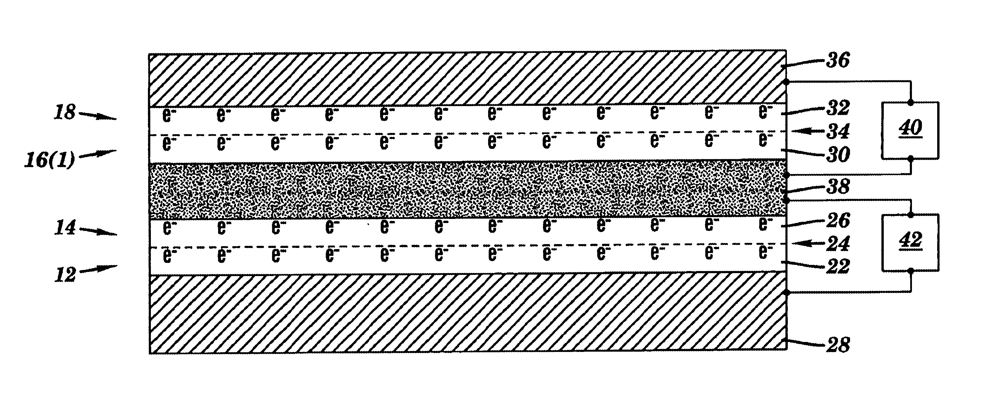
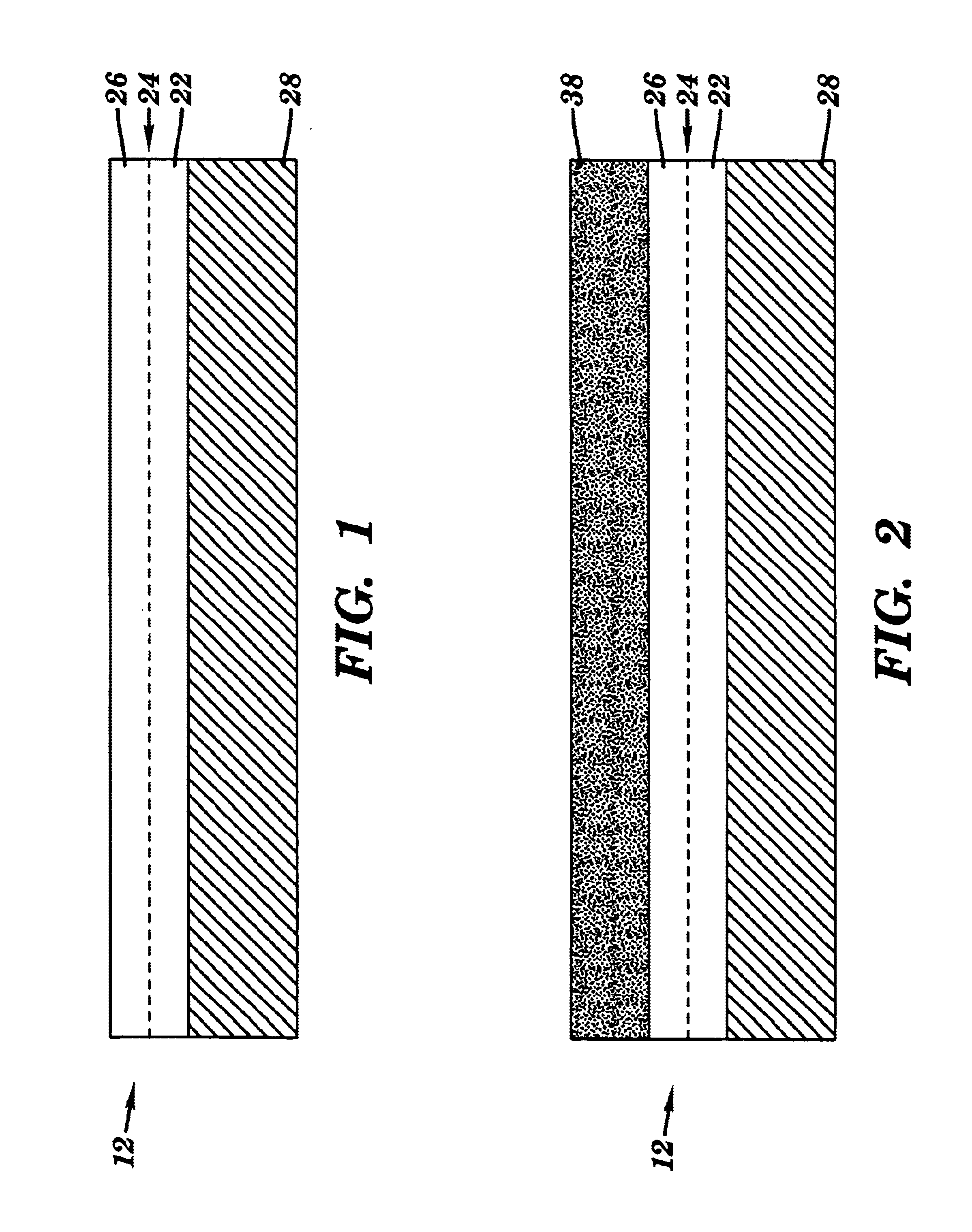
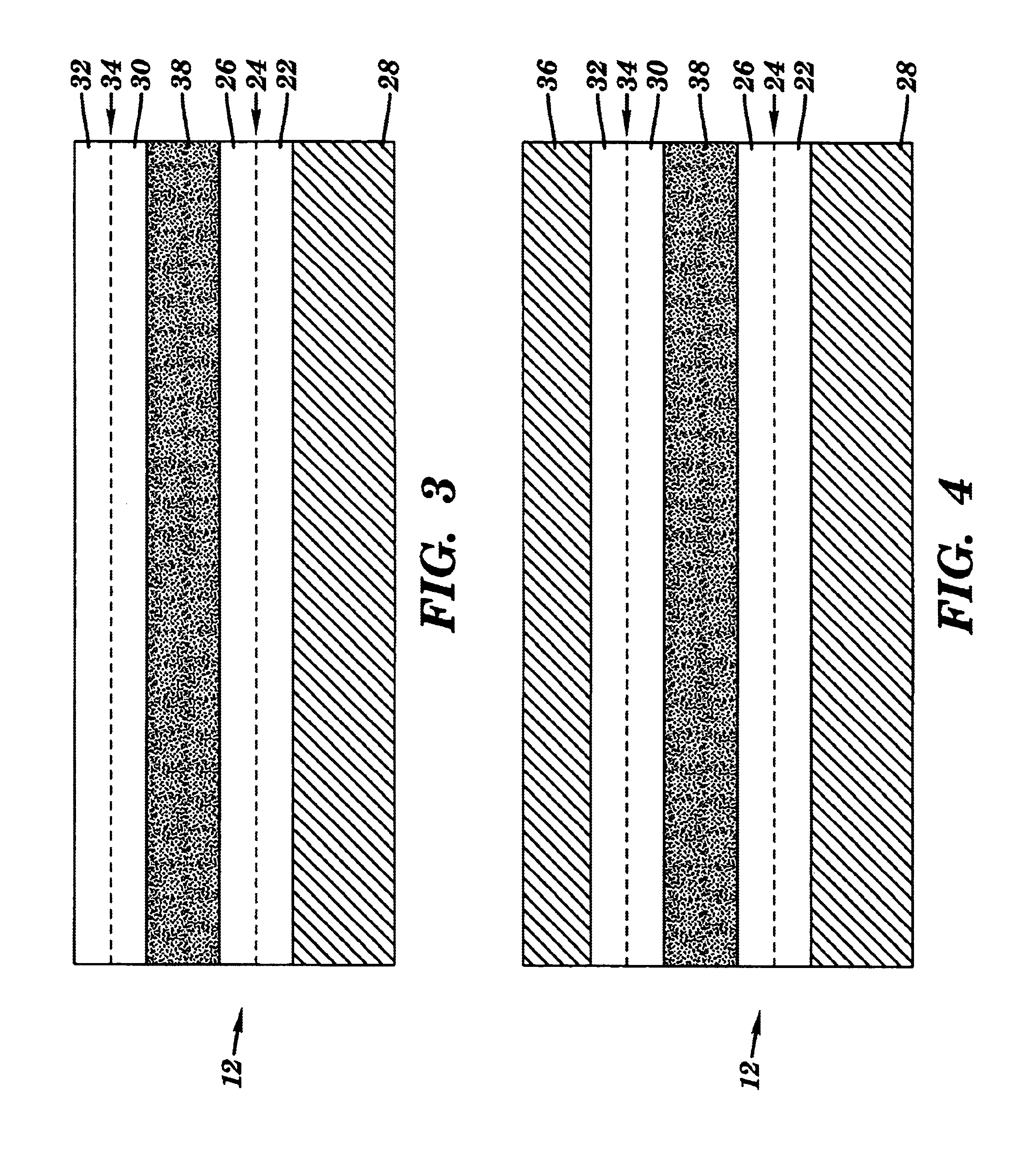
Electrostatic interaction systems 10(1)-10(3) in accordance with embodiments of the present invention are illustrated in FIGS. 6-8. The electrostatic interaction systems 10(1)-10(3) each include a first structure 12 having a first fixed electrostatic charge 14 and a second structure 16(1), 16(2), or 16(3) having a second fixed electrostatic charge 18. The polarity of the first and second fixed electrostatic charges 14 and 18 determines a positional relationship of the first structure 12 to the second structure 16(1), 16(2), or 16(3). The present invention provides electrostatic interaction systems, such as electrostatic levitation systems 10(1) and 10(2) and electrostatic attraction systems 10(3), for microscopic environments.

Referring to FIG. 6, an electrostatic levitation system 10(1) in accordance with one embodiment is illustrated. The system 10(1) may include a housing 20 for the first and second structures 12 and 16(1). A variety of different types of housings, such as a beari...


PUM

PropertyMeasurementUnit
electrostatic interactionaaaaaaaaaa
polarityaaaaaaaaaa
structuresaaaaaaaaaa

Abstract

An electrostatic interaction system includes a first structure having a first fixed electrostatic charge and a second structure having a second fixed electrostatic charge. The polarity of the first and second fixed electrostatic charges determines a positional relationship of the first structure to the second structure.

Description

FIELD OF THE INVENTIONThis invention relates to electrostatic devices and a methods and, more particularly, to electrostatic levitation and attraction systems and methods thereof.BACKGROUND OF THE INVENTIONIn the macroscopic realm, there is often an undesirable restriction of the relative movement between two surfaces. This tendency of two surfaces to stick to each other is called friction and can be significantly reduced by introducing an intermediate material, i.e. a lubricant, that is slippery between the surfaces.In the microscopic realm, there also is an undesirable restriction of the relative movement between two surfaces. Unfortunately, unlike the macroscopic realm, the introduction of an intermediate material between the surfaces may actually increase the propensity of micro components to stick together. Furthermore, in the micro and nano realms short-range forces, such as the van der Waals and electrostatic forces, become extremely important and often lead to serious limita...

Claims


Application Information

Patent Timeline
Patent Type & Authority Patents(United States)
IPC IPC(8): F16C32/00H02N1/00H02N13/00
CPCF16C32/00H02N13/00H02N1/004Y10T29/49226
Inventor POTTER, MICHAEL D.
Owner ROCHESTER INSTITUTE OF TECHNOLOGY
Learn More