
Racing game machine

a technology of racing game machines and members, applied in the field of racing game machines, can solve the problems of feedback control, large deviation from the desired direction, and member deviation, and achieve the effect of simplifying the construction of the power supply mechanism

Inactive Publication Date: 2005-01-11
KONAMI DIGITAL ENTERTAINMENT CO LTD
View PDF27 Cites 7 Cited by
  • Summary
  • Abstract
  • Description
  • Claims
  • Application Information

AI Technical Summary

Benefits of technology

The present invention is aimed at putting considerable thought into the mechanical structure and travel control mechanism of a self-propelled member, by thoroughly changing a travel driving unit and travel control method of a self-propelled member provided in a game machine, by causing a miniature to smoothly and accurately travel along a predetermined traveling path and by quickly changing the orientation of the miniature, while controlling travel of a self-propelled member without use of position detecting information.
In this configuration, the ball bearings can be utilized as power supply terminals, thereby simplifying the construction of a power supply mechanism.

Problems solved by technology

As a result of slippage, the member may be thrown into a skid and deviate from a racing track, become greatly deviated from a desired direction, or overturn.
Thus, feedback control poses a problem in the accuracy of control of a traveling route, in the response of correction of a traveling direction of a self-propelled member, and in the response of correction of a track of the self-propelled member.
Thus, difficulty is encountered in causing self-propelled members to race with each other as planned.
In this case, a control system and a control program become complicated.
Considerable difficulty is encountered in causing a plurality of self-propelled members in a game machine to accurately travel along predetermined traveling paths through feedforward control.
Causing self-propelled members to race with each other in a racing game machine through such feedforward control as planned is almost impossible.
However, in such a configuration, a position sensor, an information processing system, and a travel control system are complicated and involve considerably high manufacturing costs.

Method used


Image

  • Racing game machine
  • Racing game machine
  • Racing game machine

Examples


first embodiment

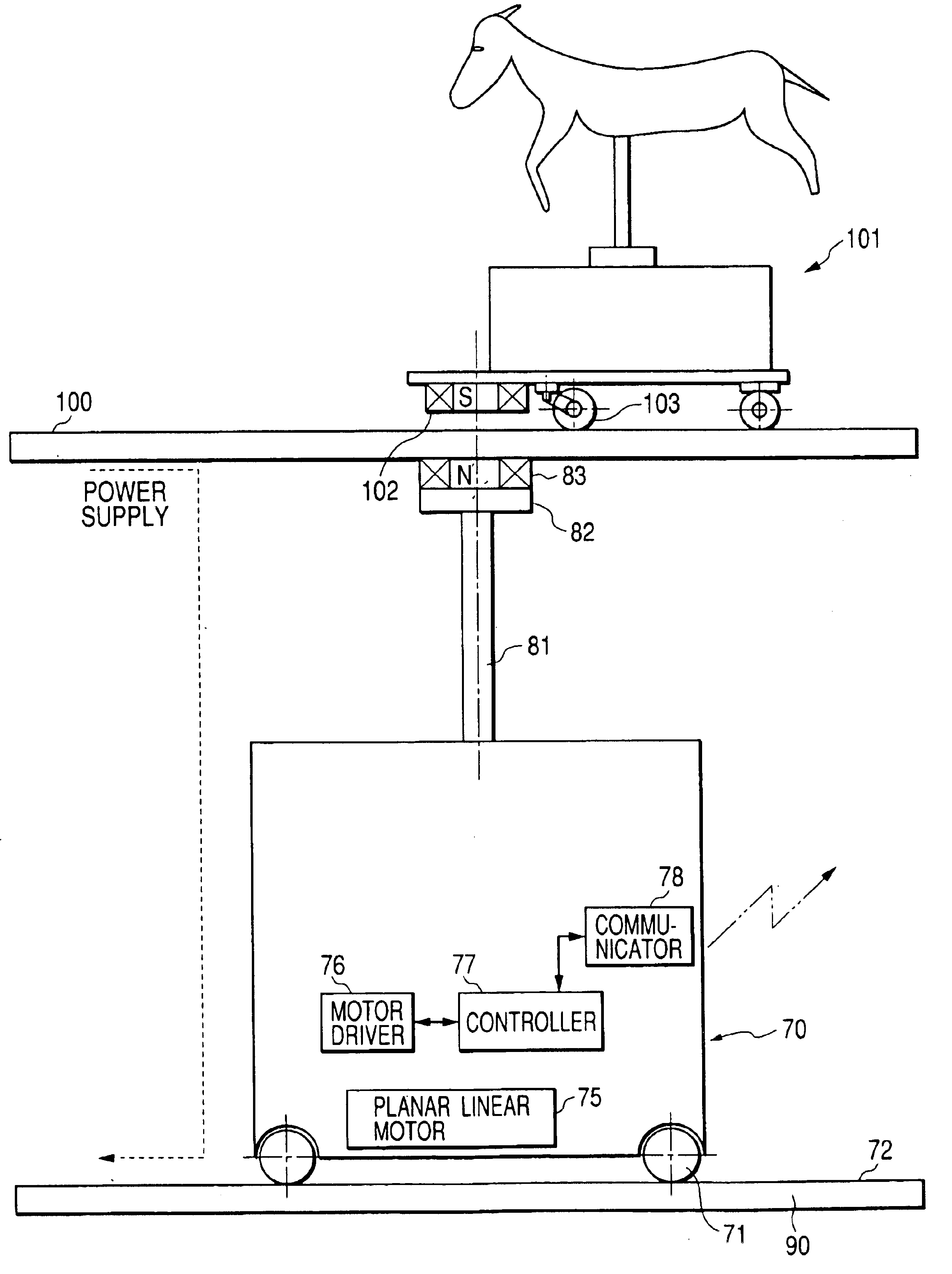
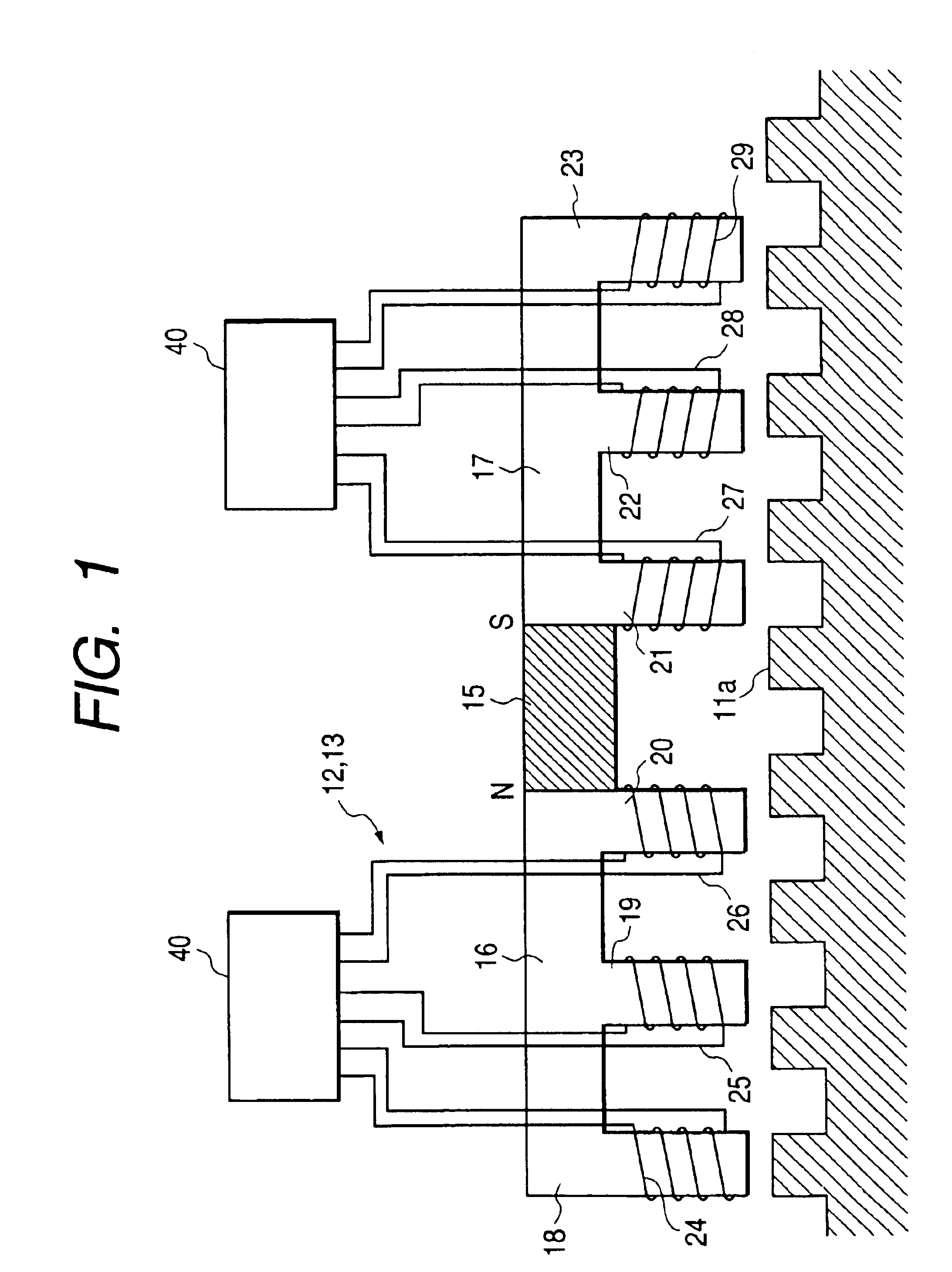
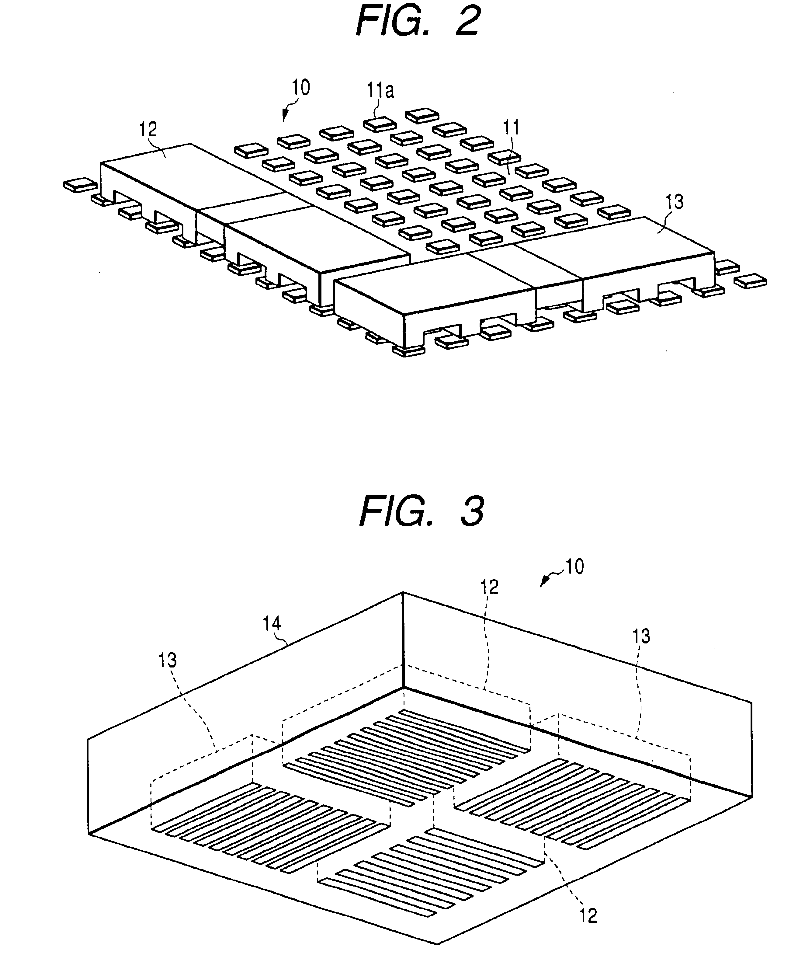
In the invention, the basic mechanism and operation principle of the travel driving device of the planar linear motor are as have been described above. A travel driving device of a self-propelled member 70 according to the present embodiment is identical with that of the above-described planar linear motor. The self-propelled member 70 travels over a traveling field 90 by four ball bearings 71 (see FIG. 9). The traveling field 90 is provided with a platen 72 having the same platen dots as those shown in FIG. 2.

A planar linear motor 75 (identical with the X-direction mobile yoke 12 and the Y-direction mobile yoke 13 shown in FIGS. 4 and 5) are provided on a lower face of the self-propelled member 70. The planar linear motor 75 is activated by a motor driver 76. A controller 77 communicates a control signal with a central controller of the game machine by way of a communicator 78, whereby the motor driver 76 is controlled by the control signal output from the central controller.

A guid...

second embodiment

FIG. 8 shows the invention, in which the guided magnet 102 is pivotably fixed on the lower face of the miniature member 101 in a forward position with a vertical pin 105. In this configuration, when a change has arisen in the traveling direction of the self-propelled member, the guided magnet 102 pivots about the vertical pin 105, and skidding in an obliquely lateral direction arises. Obliquely lateral towing force is transmitted to the miniature member via the area where the guided magnet 102 is provided. The miniature member is towed and turned in an obliquely horizontal direction. Thus, a good following performance is achieved, and it is prevented the miniature member 101 from falling on the side thereof.

In order to prevent occurrence of instability in the miniature member 101, which would otherwise be caused by downward force being exerted on the guided magnet 102 from the guide magnet 83, a ball bearing may be provided in the vicinity of the guided magnet 102 for counteracting ...

third embodiment

FIG. 12 shows the invention, in which an air bearing is adopted. In this embodiment, a compact compressor 120 is mounted on a self-propelled member 70, and the compact compressor 120 causes compressed air to blow by way of a nozzle formed in substantially the center of the lower face of the self-propelled member 70. The air is caused to flow in every direction along the lower face of the self-propelled member 70. A thin air layer (having a thickness of e.g., tens of microns) is formed between the self-propelled member 70 and a traveling face (i.e., the face of the platen 72). The self-propelled member is supported by the air layer. Since slide resistance existing between the self-propelled member 70 and the traveling face is considerably small. Hence, the self-propelled member 70 can travel considerably smoothly and freely with agility in every direction.

When a plurality of openings are formed in the lower face, the openings are arranged such that a balance is achieved with referenc...


PUM


Abstract

In a racing game machine, a traveling field, on which platen dots are provided, extends below a racing track. A plurality of self-propelled members are provided on the traveling field. Each self-propelled member includes a first linear motor a second linear motor for propelling the self-propelled member in an arbitrary direction on the traveling field, and includes a first magnet provided in an upper portion thereof. A plurality of miniature members are provided on the racing track to be raced with each other, while being associated with the respective self-propelled members. Each miniature member includes front wheels and rear wheels provided on a bottom face thereof for supporting the miniature member on the racing track. The front wheels are provided as caster wheels. A second magnet is provided in a front side of the caster wheels while being magnetically coupled with the first magnet.

Description

BACKGROUND OF THE INVENTIONThe present invention relates to a game machine using self-propelled members, and more particularly, to a racing game machine which facilitates travel control of the self-propelled members, significantly simplifies a mechanical structure and control system of the game machine, and significantly curtails manufacturing costs.A travel driving mechanism of a self-propelled member used in a racing game machine basically drives wheels by a rotary drive motor and effects turning action by controlling a rotational speed differential between the left driving wheel and the right driving wheel. Japanese Patent No. 2650643 discloses an example of such a racing game machine. In the racing game machine, a racing track is formed into a two-story structure in which self-propelled members are caused to travel on a traveling field to attractively guide miniatures which are incapable of self-propelling are caused to race with each other on a racing track by way of magnetic f...

Claims


Application Information

Patent Timeline
Patent Type & Authority Patents(United States)
IPC IPC(8): A63F9/14A63H18/00
CPCA63F9/143A63H18/00
Inventor KOBAYASHI, YUSUKE
Owner KONAMI DIGITAL ENTERTAINMENT CO LTD
Learn More