Radial indexing head tool with floating splined pin

a technology of radial indexing head and spline pin, which is applied in the direction of manufacturing tools, couplings, rod connections, etc., can solve the problems of difficult engagement and disengagement of couplers, many disadvantages of existing devices, and awkward use of devices in close areas

Inactive Publication Date: 2005-01-11
COLE BRIAN T +1
View PDF83 Cites 18 Cited by
  • Summary
  • Abstract
  • Description
  • Claims
  • Application Information

AI Technical Summary

Problems solved by technology

However, existing devices suffer from many disadvantages.
In many coupling devices, it is difficult to engage and disengage the coupler.
This can be very awkward when utilizing the devices in close areas.
In addition, when pressing the coupling device to engage or disengage, the existing devices t

Method used


Image

  • Radial indexing head tool with floating splined pin
  • Radial indexing head tool with floating splined pin
  • Radial indexing head tool with floating splined pin

Examples


Embodiment Construction

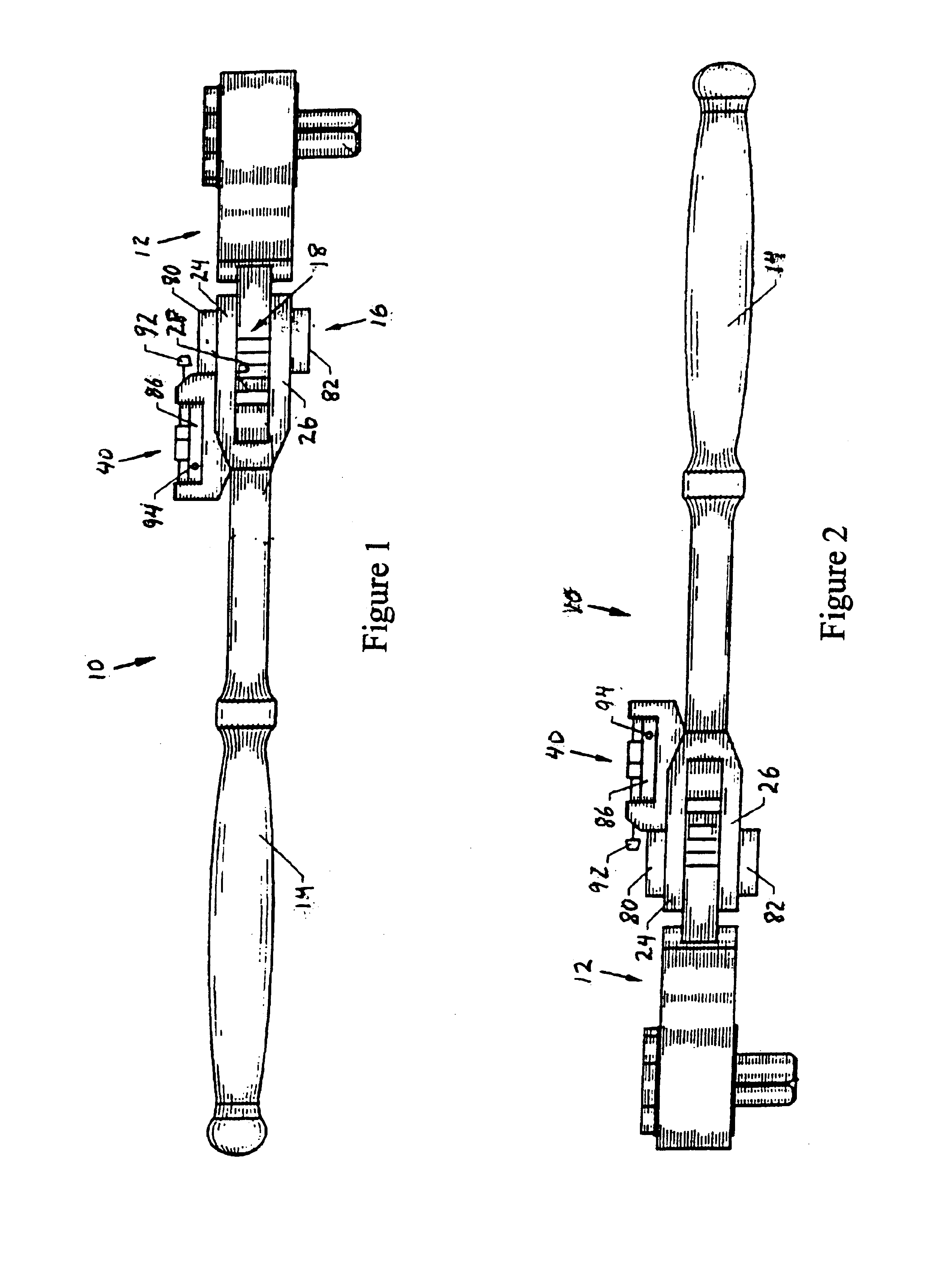
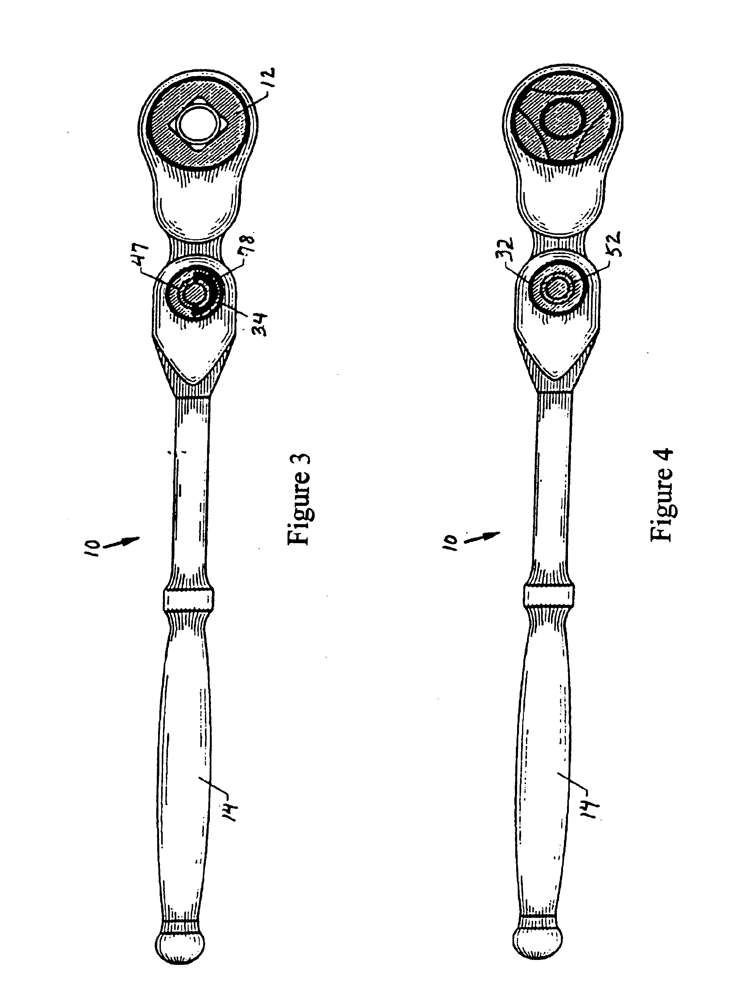
A radial indexing head tool with a floating splined pin 10 embodying certain features of the present invention, as illustrated in FIGS. 1-5, includes a tool head 12 coupled to a handle 14 by a splined pin assembly 16. The tool head 12, illustratively a ratchet head, includes an attaching member 18 having a splined orifice 22. The handle 14 includes an upper prong 24 and a lower prong 26. The prongs 24, 26 are disposed in spaced-apart relation with a gap 28 therebetween for receiving the tool head-attaching member 18. The upper and lower prongs 24, 26 include splined orifices 32, 34, respectively, that coaxially align with the splined orifice 22 of the tool head 12. A locking device 40 is disposed on the handle 14 to engage the splined pin assembly 16 to lock and unlock the indexable wrench 10.

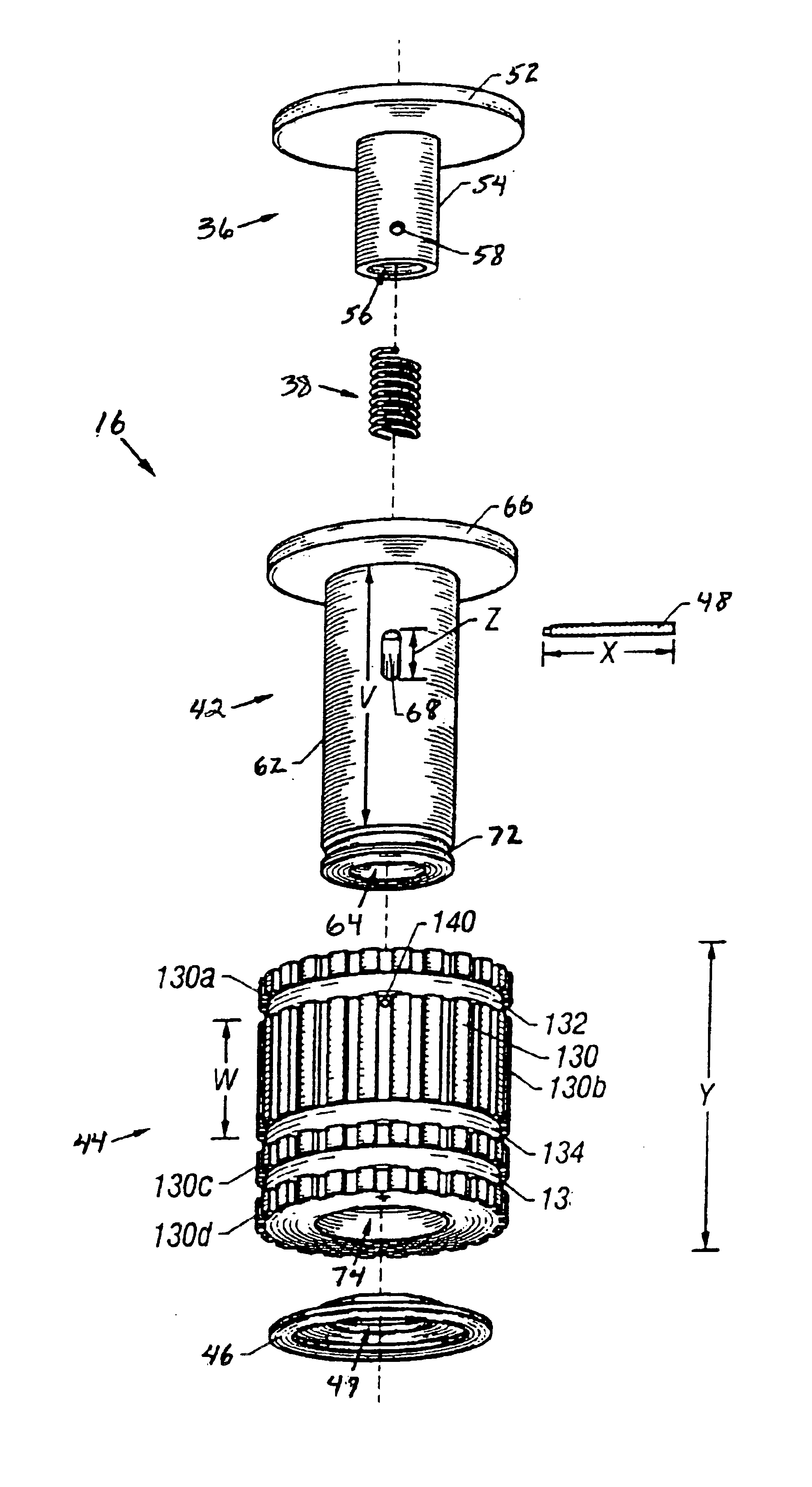
As illustrated in FIG. 6, the splined pin assembly 16 includes a plunger 36, a coil spring 38, an axial retainer 42, a splined cylinder 44, a washer 46, and a retaining pin 48.

The plunger 36 in...


PUM


Abstract

A radial indexing head tool includes a handle and ratchet head, each with a splined orifice, and a floating splined pin disposed in the splined orifices for coupling them together. The floating splined pin includes a cylindrical axial retainer coupled to the handle and extending into the splined orifices, a plunger configured for axial movement within the axial retainer, and a splined cylinder configured for axial movement along the outside of the axial retainer within the splined orifices. The plunger and splined cylinder are coupled to each other through the cylindrical wall of the retainer. Movement of the splined cylinder aligns or misaligns grooves and splined portions formed on the splined cylinder relative to grooves and splined portions formed in the splined orifices to lock or unlock the ratchet head for movement relative to the handle.

Description

The present invention relates to hand tools and particularly to hand tools having members coupled together for movement relative to each other. More particularly, the invention relates to a splined pin for coupling the members.BACKGROUND OF THE INVENTIONDevices for coupling two members together are well known. Many of these devices allow members to be coupled and adjusted to a desired position. However, existing devices suffer from many disadvantages. In many coupling devices, it is difficult to engage and disengage the coupler.For example, in some existing devices, the coupler must be physically pressed to lock or unlock the coupler. This can be very awkward when utilizing the devices in close areas. In addition, when pressing the coupling device to engage or disengage, the existing devices tend to bind.A device is needed which couples two members together, allows the coupler to be easily engaged and disengaged, and does not bind.One solution to the aforementioned deficiency was di...

Claims


Application Information

Patent Timeline
IPC IPC(8): B25G1/00B25G1/06
CPCB25G1/063Y10T403/32368Y10T403/559
Inventor COLE, CHARLES A.
Owner COLE BRIAN T
Why Eureka
Try Eureka