
PEMF stimulator for treating osteoporosis and stimulating tissue growth

a stimulator and osteoporosis technology, applied in magnetotherapy, magnetotherapy using coils/electromagnets, magnetotherapy, etc., can solve the problems of loss of bone mineral density, un-united fractures, and musculoskeletal system, and achieve the disadvantages and problems of conventional flats

Inactive Publication Date: 2005-01-04
AMEI TECH
View PDF32 Cites 46 Cited by
  • Summary
  • Abstract
  • Description
  • Claims
  • Application Information

AI Technical Summary

Benefits of technology

In accordance with the teachings of the present invention, disadvantages and problems associated with the use of conventional flat or oval shaped coils or utilization of both a primary and secondary coil design have been substantially reduced or eliminated.
One aspect of the present invention includes a method of using the electronic therapy apparatus as a bone mineral density (BMD) stimulator for osteoporotic patients. The stimulator for this embodiment may sometimes be referred to as a PEMF stimulator or Osteoporosis stimulator. The stimulator generates a pulsed electromagnetic field (PEMF) which induces voltages and current to provide non-invasive treatment to increase bone mineral density (BMD). The pulsed electromagnetic field generated by the bone mineral density stimulator, provides a non-invasive treatment for osteoporosis. The signal may be of a similar frequency as that delivered by commercially available stimulators which have been clinically demonstrated to affect bone formation. The signal offers greater energy efficiency than many current commercial PEMF devices.
One or more embodiments of the present invention may include some, none, or all of the following technical advantages. These technical advantages may include using PEMF therapy to increase bone density to a level that substantially decreases a patient's risk of fracture. For example, treatment over a broad field that would encompass all areas of bone particularly prone to osteoporotic fracture, including but not limited to areas such as the hip, spine and wrists, would be beneficial in increasing bone mineral density and / or content, thereby preventing osteoporotic fracture. Another technical advantage may include a synergistic effect when PEMF therapy is used in combination with pharmaceutical therapy. Yet another technical advantage may include using PEMF therapy to provide a patient a single daily treatment to simultaneously treat areas subject to fracture. The cost of such PEMF therapy is substantially reduced as compared to the cost associated with pharmaceutical treatment of osteoporosis. Such PEMF therapy may provide a suitable replacement therapy for patients who cannot be treated with pharmaceuticals. A bone mineral density stimulator incorporating teachings of the present invention may be used for prevention of hip, spinal, wrist and / or other fractures.
Further technical advantages of the present invention may include producing an energy efficient PEMF signal with pulse period between ten microseconds (10 μsec) and twenty microseconds (20 μsec). For some applications, a bone mineral density stimulator producing a PEMF signal with a pulse period of approximately sixteen microseconds (16 μsec) will be energy efficient.

Problems solved by technology

Therapeutically difficult problems of the musculoskeletal system include spinal fusion, un-united fractures (or non-union fractures), failed arthrodeses, osteonecrosis, and chronic refractory tendonitis, decubitus ulcers and ligament, tendon injuries, osteoporosis, and Charcot foot.
Such problems, especially fractures, may result from losses in bone mineral density.
This approach is disadvantageous because such therapy is generally expensive, and lasts for a patient's lifetime.
Furthermore, such therapy may be associated with side effects which some patients may not tolerate.
This approach is disadvantageous because the transducer coil may not cover the entire treatment area and the applied field has limited penetration.

Method used


Image

  • PEMF stimulator for treating osteoporosis and stimulating tissue growth
  • PEMF stimulator for treating osteoporosis and stimulating tissue growth
  • PEMF stimulator for treating osteoporosis and stimulating tissue growth

Examples


Embodiment Construction

The preferred embodiments of the present invention and its advantages are best understood by referring now in more detail to FIGS. 1A-10C of the drawings, in which like numerals refer to like parts.

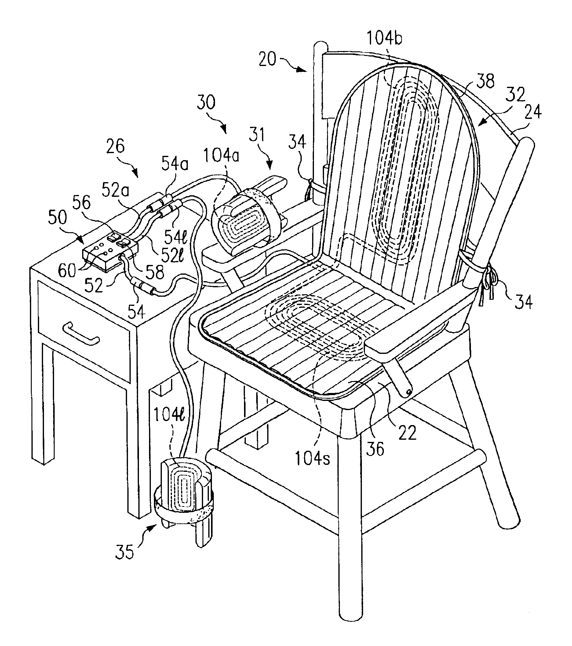
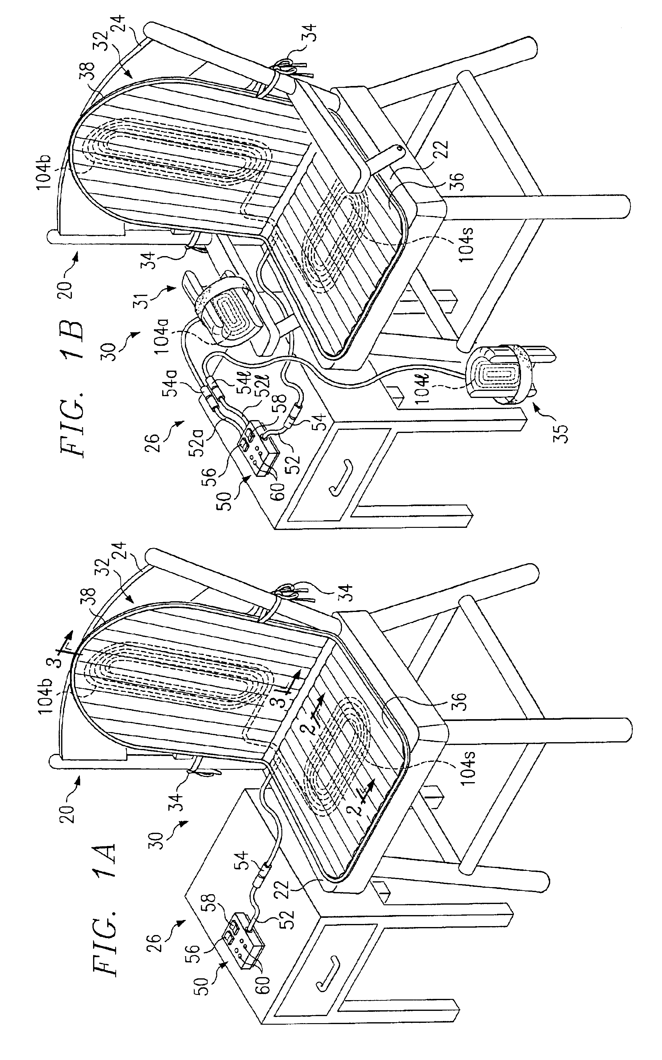
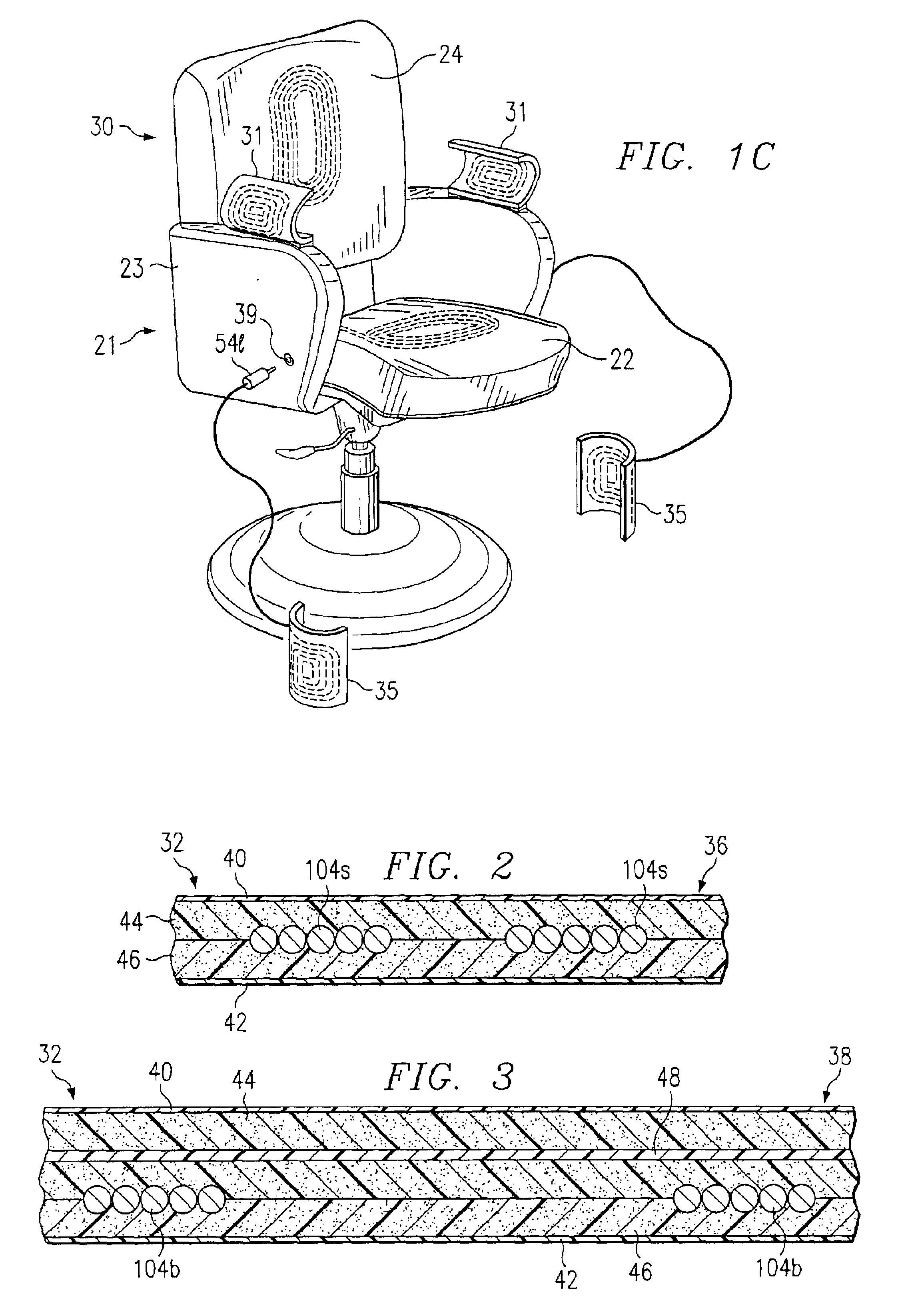
Bone mineral density stimulator 30 incorporating teachings of the present invention is shown in FIG. 1A secured to chair 20. Bone mineral density stimulator 30 produces electrical signals similar to Spinal-Stim® Lite devices that are offered by Orthofix. In operation, bone mineral density stimulator 30 includes a control unit or housing 50 sending a programmed signal to at least two transducer coils 104s and 104b. The PEMF signal generated by bone mineral density stimulator 30 may consist of a burst of one thousand six hundred nine (1609) pulses, at a repetition rate of one and one-half (1.5) pulse bursts per second. Each individual pulse consists of a positive (energization) portion, four microseconds (4 μsec) wide, and a negative (de-energization) portion, approximately twelve microseco...


PUM


Abstract

A method for providing electromagnetic therapy to a patient includes placing the patient in proximity to an electromagnetic therapy apparatus. The electromagnetic therapy apparatus includes an electrical circuit for generating an electrical drive signal, a first transducer coil and a second transducer coil for generating respective electromagnetic fields in response to the drive signal, a first portion with a configuration corresponding generally with a chair seat, and a second portion with a configuration corresponding generally with a chair back. The first transducer coil is disposed within the first portion and the second transducer coil is disposed within the second portion. The method further includes stimulating the patient with a pulsed electromagnetic field from at least the first and second transducer coils. The pulsed electromagnetic field having a number of pulses, each pulse having a pulse period of ten microseconds to twenty microseconds.

Description

TECHNICAL FIELD OF THE INVENTIONThe present invention relates generally to a PEMF stimulator for treating osteoporosis and other medical conditions by promoting an increased bone mineral content and density.BACKGROUND OF THE INVENTIONTherapeutically difficult problems of the musculoskeletal system include spinal fusion, un-united fractures (or non-union fractures), failed arthrodeses, osteonecrosis, and chronic refractory tendonitis, decubitus ulcers and ligament, tendon injuries, osteoporosis, and Charcot foot. Such problems, especially fractures, may result from losses in bone mineral density. Osteoporosis in particular is responsible for 1.5 million fractures in the U.S. annually, especially hip, vertebral and wrist fractures. One conventional approach for treating such fractures is pharmaceutical therapy. This approach is disadvantageous because such therapy is generally expensive, and lasts for a patient's lifetime. Furthermore, such therapy may be associated with side effects ...

Claims


Application Information

Patent Timeline
Patent Type & Authority Patents(United States)
IPC IPC(8): A61N2/02A61N2/00A61N1/40A61N2/04
CPCA61N2/02
Inventor TEPPER, JOHN C.KUO, PETERMCDERMOTT, KATHY L.
Owner AMEI TECH
Learn More