
Safety shield assembly

a safety shield and assembly technology, applied in the field of safety shields, can solve the problems of preventing the use of devices, affecting the closure of some current shielding structures, and cumbersome current shielding structures, and achieve the effect of convenient needle maneuverability

Inactive Publication Date: 2005-01-04
BECTON DICKINSON & CO
View PDF51 Cites 139 Cited by
  • Summary
  • Abstract
  • Description
  • Claims
  • Application Information

AI Technical Summary

Benefits of technology

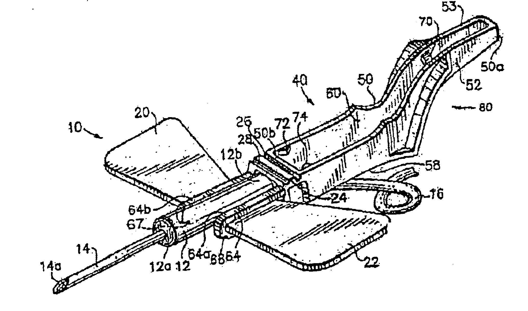
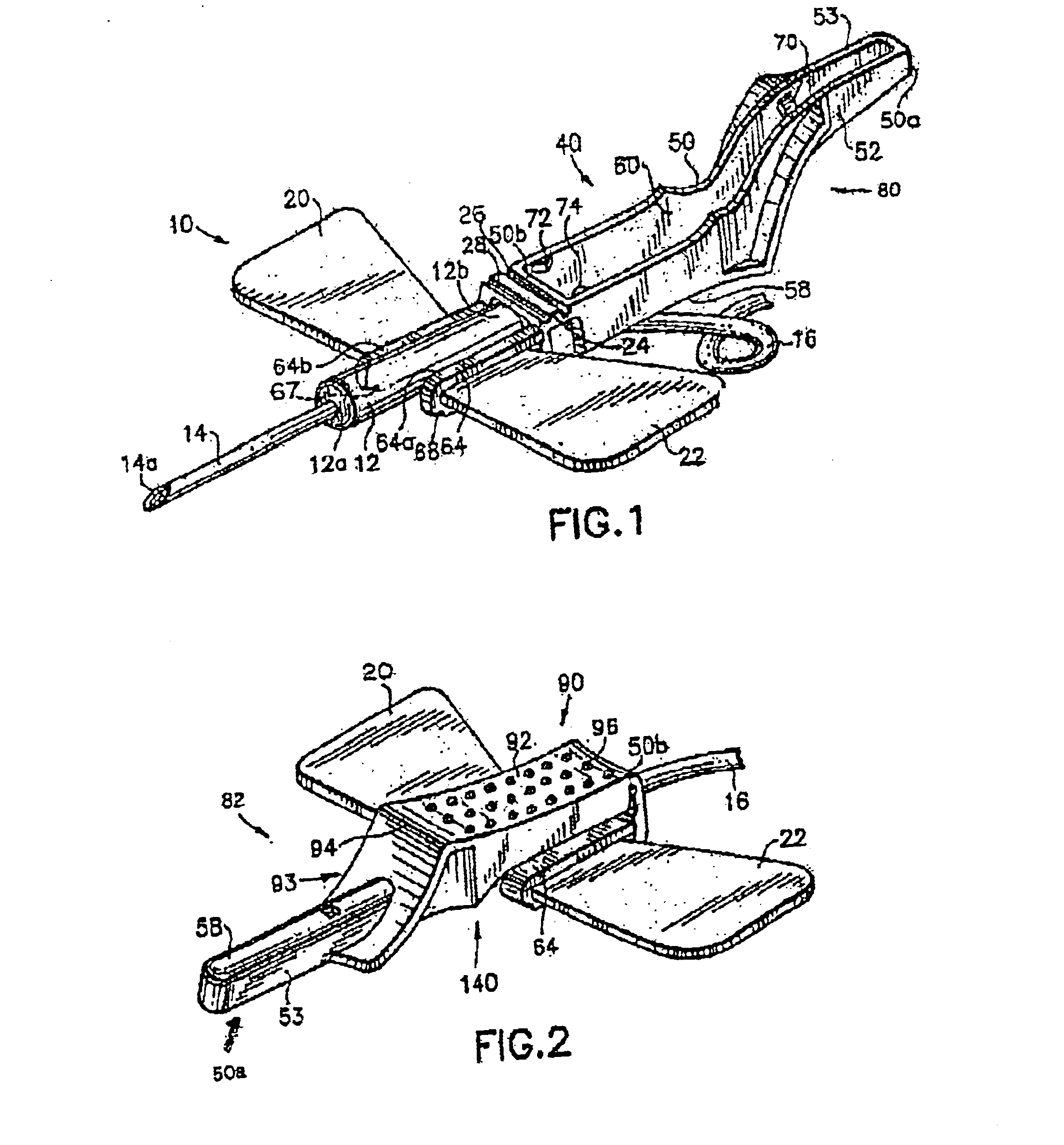
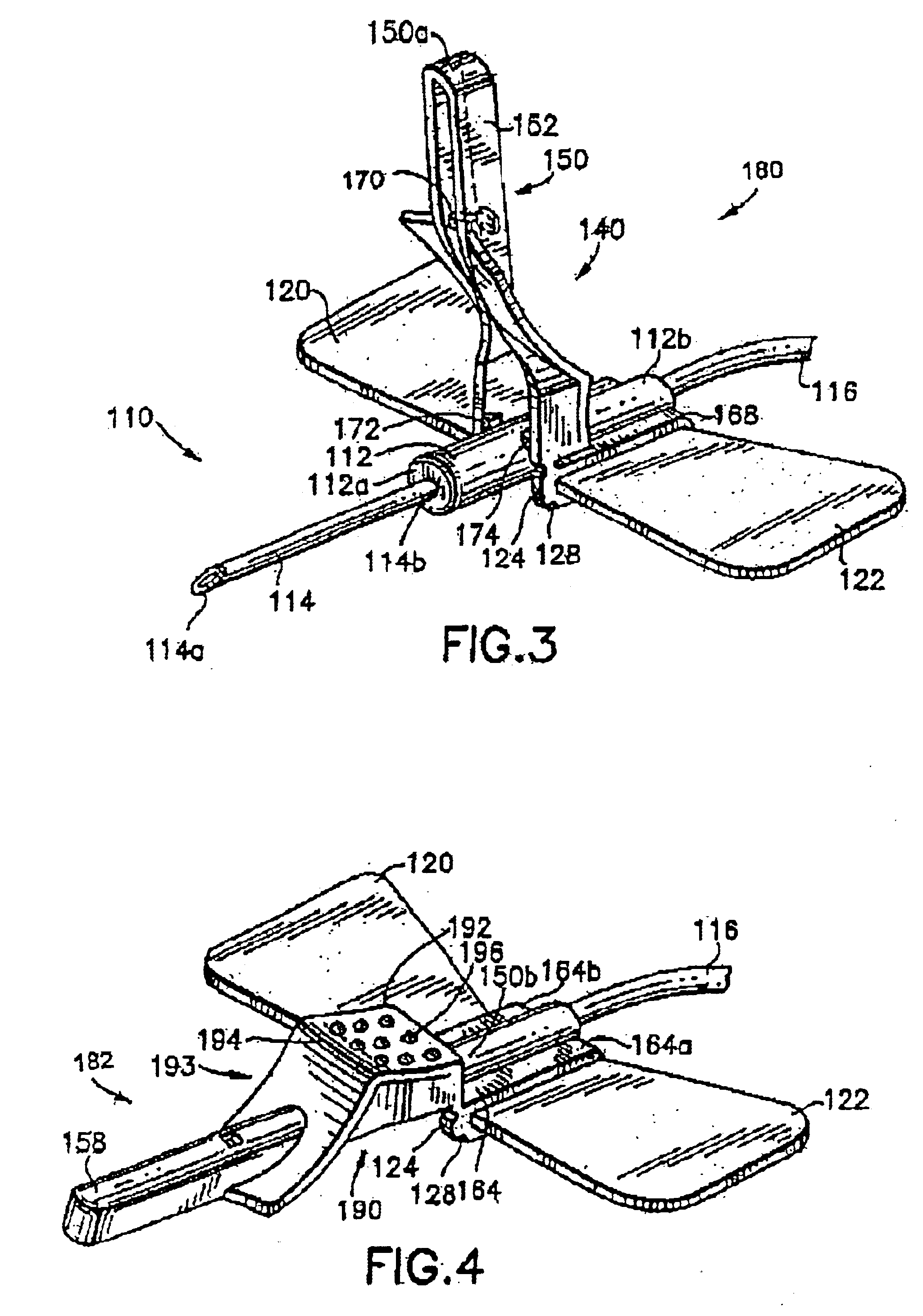
The present invention provides an IV infusion and blood collection assembly with a safety shield that does not interfere with normal practices of needle use. The shield is easy to use, cost efficient to manufacture, and provides increased safety to the user. The assembly includes an elongate needle, a length of tubing, and an elongate housing supporting the needle at one end and the tubing at the other end in fluid communication. The housing includes a pair of opposed outwardly extended wings. The assembly further includes a shield pivotally secured to the housing for pivotal movement from a position away from the needle to a position enclosing the needle. The shield is mounted to the housing by use of clips which may be secured to the housing. The shield sidewalls have protrusions for engaging the clips or housing when the shield is in the enclosed position over the needle, locking the shield. The shield is designed to securely hold the needle and prevent accidental sticks.

Problems solved by technology

Current shielding structures for IV infusion or blood collection assemblies are often cumbersome, expensive and complex.
In fact, the wings of these assemblies may interfere with the closure of some of the current shielding structures.
Additionally, some of the current shielding structures may interfere with the normal and accepted procedure of one handed needle placement techniques or are so complex that they preclude use of the device in certain procedures or with certain devices and / or assemblies.

Method used


Image

  • Safety shield assembly
  • Safety shield assembly
  • Safety shield assembly

Examples


Embodiment Construction

While this invention is satisfied by embodiments in many different forms, there is shown in the drawings and will herein be described in detail preferred embodiments of the invention, with the understanding that the present disclosure is to be considered as exemplary of the principles of the invention and is not intended to limit the invention to the embodiments illustrated. Various other modifications will be apparent to and readily made by those skilled in the art without departing from the scope and spirit of the invention. The scope of the invention will be measured by the appended claims and their equivalents.

A convention adopted for this disclosure is that the term “distal” or “needle end” refers to the direction away from the user or practitioner and the term “proximal” or “non-patient end” refers to the direction toward the user. Additionally, as used throughout this disclosure, the term “needle” is intended to encompass the broad range of penetration fluid delivery elements...


PUM


Abstract

An intravenous (IV) infusion and / or blood collection assembly including a safety shield. The shield is particularly useful with winged needle assemblies. The shield is pivotally secured to the winged needle assembly to enable pivotal movement from a position away from the needle to a position enclosing the needle. The shield is lockable in a position over the used needle to prevent the user from contacting the used needle.

Description

BACKGROUND OF THE INVENTION1. Field of the InventionThe present invention relates to intravenous infusion and blood collection assemblies and more particularly, intravenous infusion and blood collection assemblies with a safety shield. In particular, the present invention relates to a safety device for winged needle assemblies.2. Description of Related ArtA conventional intravenous (IV) infusion or blood collection assembly usually includes an elongated small gauged plastic flexible tubing material having at one end thereof a disposable needle and a body or housing for holding the needle. Usually, the needle body is adhered to one end of the flexible tube by friction. The needle body includes wings extending on either side for the phlebotomist or user to grasp or hold the needle body for inserting the needle into a patient. Additionally, wings enable improved angles of penetration of the needle. Such assemblies may be used for infusing medication into a patient or for collecting blo...

Claims


Application Information

Patent Timeline
Patent Type & Authority Patents(United States)
IPC IPC(8): A61B5/15A61M25/06A61M5/31A61M5/32A61M5/158
CPCA61B5/1438A61M25/0631A61M25/0637A61M5/3216A61M25/0612Y10S128/919A61M2005/3109A61M2205/582A61M2205/583A61B5/15003A61B5/150259A61B5/150389A61B5/150503A61B5/150595A61B5/150671A61B5/15074A61B5/150816A61B5/153
Inventor ZURCHER, ROBERT
Owner BECTON DICKINSON & CO
Learn More