
Harvesting equipment

a technology for harvesting equipment and chain elements, applied in the direction of agricultural lifting devices, machinery, lawnmowers, etc., can solve the problems increasing the difficulty of maintenance and exchange of chain elements, and increasing the risk of blockage of conveying chains. , to achieve the effect of reducing the danger of blockage of conveying chains and facilitating widening or shortening the chain

Inactive Publication Date: 2005-01-04
MASCHFAB BERNARD KRONE GMBH
View PDF5 Cites 7 Cited by
  • Summary
  • Abstract
  • Description
  • Claims
  • Application Information

AI Technical Summary

Benefits of technology

The invention is about improving the ease of maintaining and handling harvesting equipment. The invention achieves this by making the equipment easier to modify for different working widths. The chain elements in the equipment are designed to prevent blockage and wear is reduced when the chain elements have deflection plates. The invention also includes an attachment with two link chains revolving in opposite directions. The attachment has a uniform function body with several holding planes and deflection plates to prevent cut off stalks from falling out of the cutter bar. Overall, the invention makes the harvesting equipment more efficient and durable.

Problems solved by technology

Such conveying chains are subject to the danger of blockage by harvested crops engaging between the flat links.
These chains are therefore subjected to considerable wear.
Moreover, the maintenance and exchange of chain elements is made more difficult by the superimposed cutting and holding tools.

Method used


Image

  • Harvesting equipment
  • Harvesting equipment
  • Harvesting equipment

Examples


Embodiment Construction

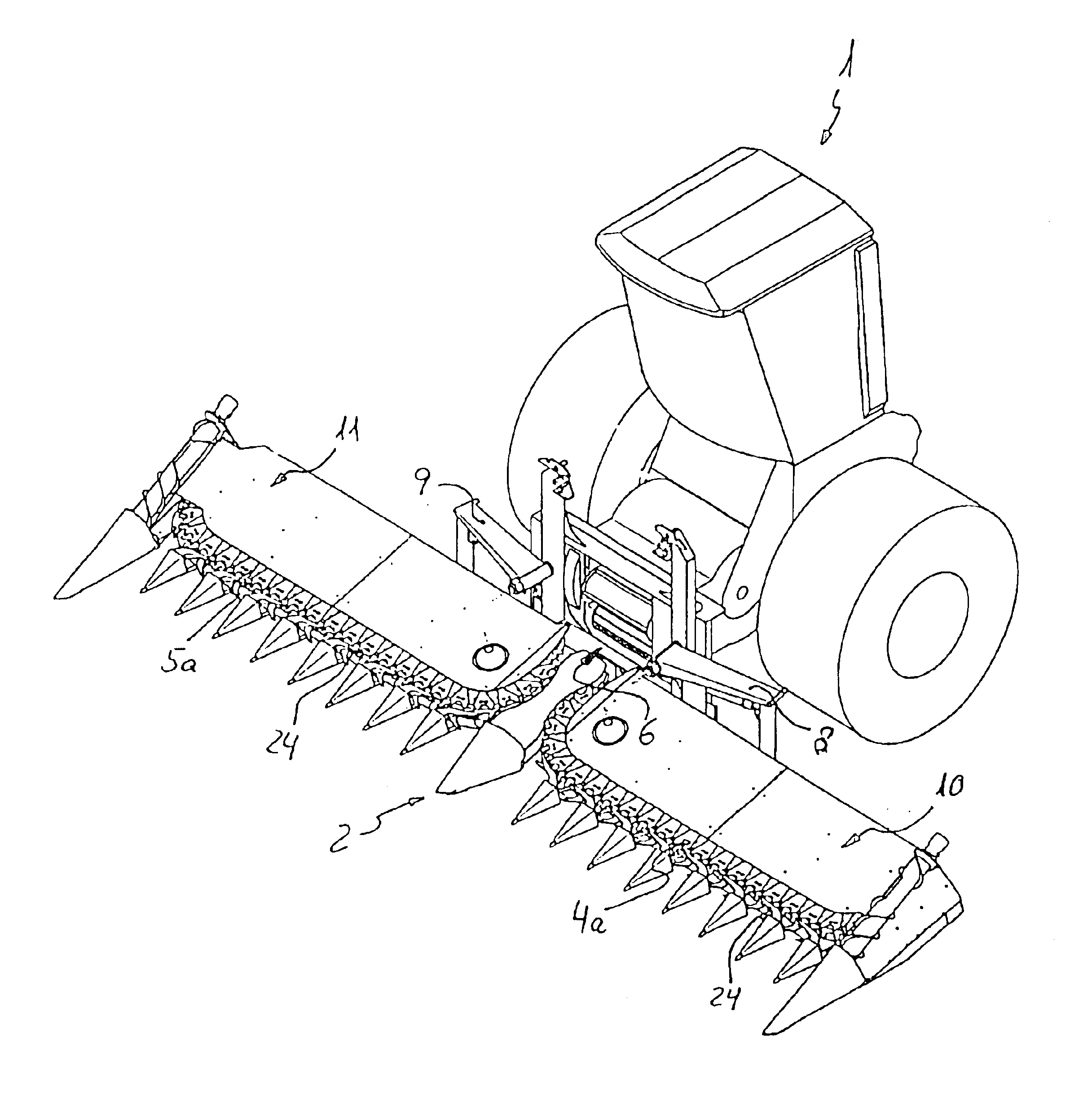
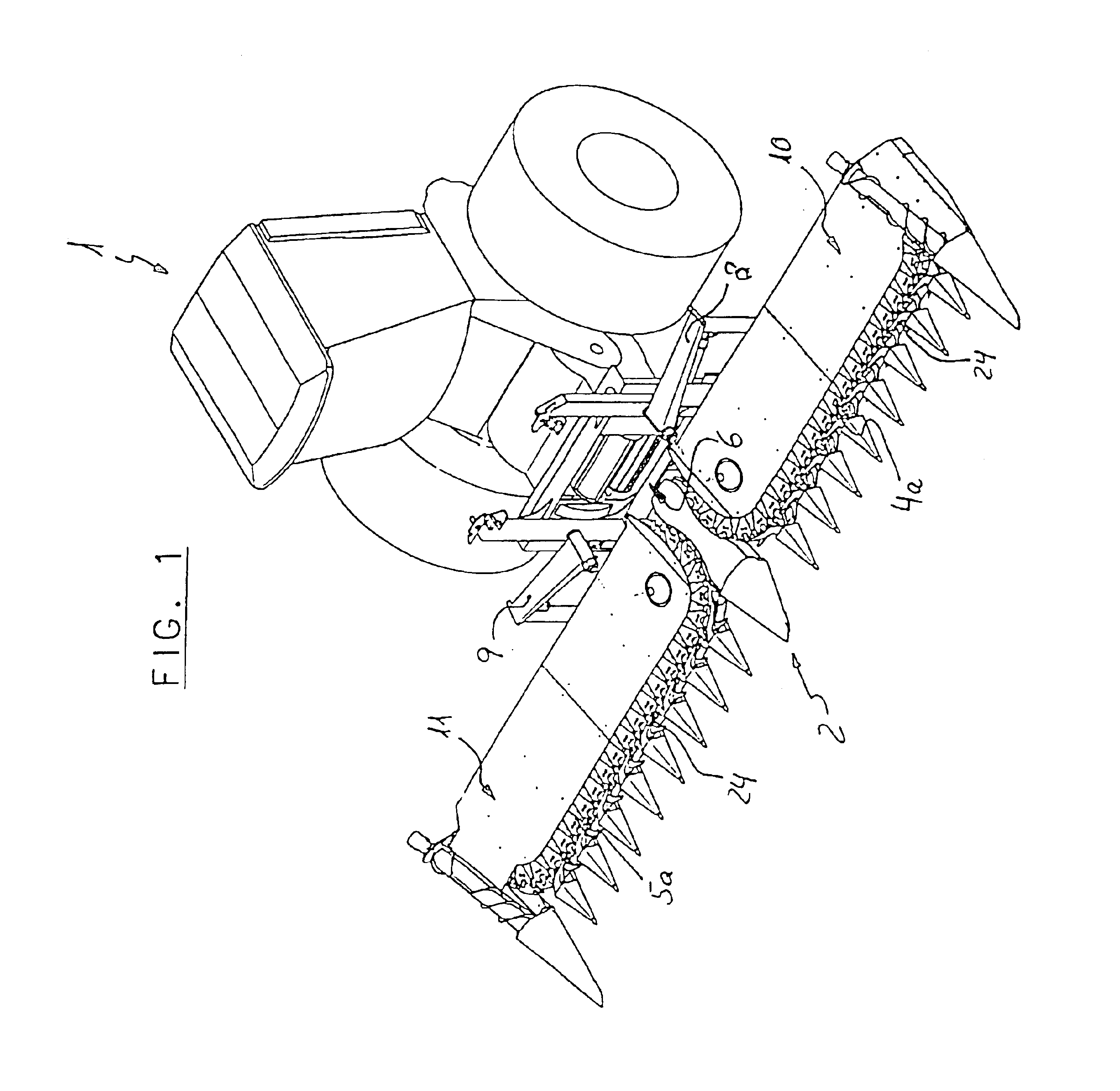
According to the example, the harvesting equipment 1 is constructed as a self-propelled vehicle and comprises an attachment 2, which takes up the harvested crop 3 over two link chains 4, 5 and supplies it to an inlet opening 6 of a chopper or a different device, which processes it further. The link chains 4, 5 run in the directions of the arrows U1 and U2 with their tight side 4a or 5a on a vertical, longitudinal center plane of the harvesting equipment. With that, a strip of harvested products can be harvested with a harvesting equipment 1 can also be used equally well independently of rows. As a rule, however, corn fields are planted and harvested in rows. This offers the advantage that automatic steering can be used for the harvesting equipment 1, which identifies the position of the rows 3a and guides the harvesting equipment 1 correspondingly. Moreover, when corn is harvested, an accumulation of soil may be found in the area of the corn rows 3a, which, when driven over obliquel...


PUM


Abstract

Harvesting equipment (1) for harvesting corn or similar stalk-like harvested products, the harvesting equipment (1) having at least one link chain (4; 5), which is provided with holding means for the cut-down harvested products (3), and has a tight side (4a; 5a) which can be moved, when in use, transversely to the driving direction (F) of the harvesting equipment (1), is constructed so that the extent (T) of an element (14, 15) of the link chain (4; 5), measured in the revolving direction (U1; U2), essentially corresponds to a whole number divider of a standard distance between rows (3a) of harvested products (3) cultivated, in a standardized manner.

Description

BACKGROUND OF THE INVENTIONThe invention relates to harvesting equipment for harvesting corn or similar stalk-like harvested crops.The DE 33 24 899 C2 discloses generic harvesting equipment, for which the harvested crops are cut off by cutting tools suspended in a flat link articulated chain and conveyed by holding means, which are furthermore suspended in the flat link articulated chain, to an inlet opening of a chopper or the like. Such conveying chains are subject to the danger of blockage by harvested crops engaging between the flat links. These chains are therefore subjected to considerable wear. Moreover, the maintenance and exchange of chain elements is made more difficult by the superimposed cutting and holding tools.SUMMARY OF THE INVENTIONIt is therefore an object of the invention to improve the ease of maintaining and handling such harvesting equipment. Pursuant to the invention, this objective is accomplished by harvesting equipment with the distinguishing features of cl...

Claims


Application Information

Patent Timeline
Patent Type & Authority Patents(United States)
IPC IPC(8): A01D43/08A01D43/00A01D65/00A01D45/02
CPCA01D65/00A01D43/082
Inventor KRONE, BERNARDAHLER, WILHELMKELLER, ALFONS
Owner MASCHFAB BERNARD KRONE GMBH
Learn More