
Endocardial mapping catheter

a technology of endocardial surface and catheter, which is applied in the field of endocardial mapping catheter, can solve the problems of inability to accurately resolve the location of ectopic tissue masses, inability to accurately resolve the location of two-dimensional maps of electrical potentials at the endocardial surface generated by these traditional processes, and many defects

Inactive Publication Date: 2004-11-30
ST JUDE MEDICAL ATRIAL FIBRILLATION DIV
View PDF3 Cites 111 Cited by
  • Summary
  • Abstract
  • Description
  • Claims
  • Application Information

AI Technical Summary

Benefits of technology

The present invention provides a method for creating a detailed map of the electrical activity of the heart using a specialized catheter system. The system allows for the visualization of the location of catheter electrodes in a three-dimensional map. Additionally, the invention can provide a two-dimensional map of the electrical potential at or below the myocardial tissue surface. The invention can be used to diagnose and treat various heart conditions. The patent text describes the system and method, as well as the drawings and modifications that can be made to the invention.

Problems solved by technology

The two-dimensional maps of the electrical potentials at the endocardial surface generated by these traditional processes suffer many defects.
Traditional systems have been limited in resolution by the number of electrodes used.
The small number of signals from the endocardial wall will result in the inability to accurately resolve the location of ectopic tissue masses.
Such interpolated two-dimensional maps have significant deficiencies.
First, if a localized ectopic focus is between two electrode views such a map will at best show the ectopic focus overlaying both electrodes and all points in between and at worst will not see it at all.
Second, the two dimensional map, since it contains no chamber geometry information, cannot indicate precisely where in the three dimensional volume of the heat chamber an electrical signal is located.
The inability to accurately characterize the size and location of ectopic tissue frustrates the delivery of certain therapies such as "ablation".

Method used


Image

  • Endocardial mapping catheter
  • Endocardial mapping catheter
  • Endocardial mapping catheter

Examples


Embodiment Construction

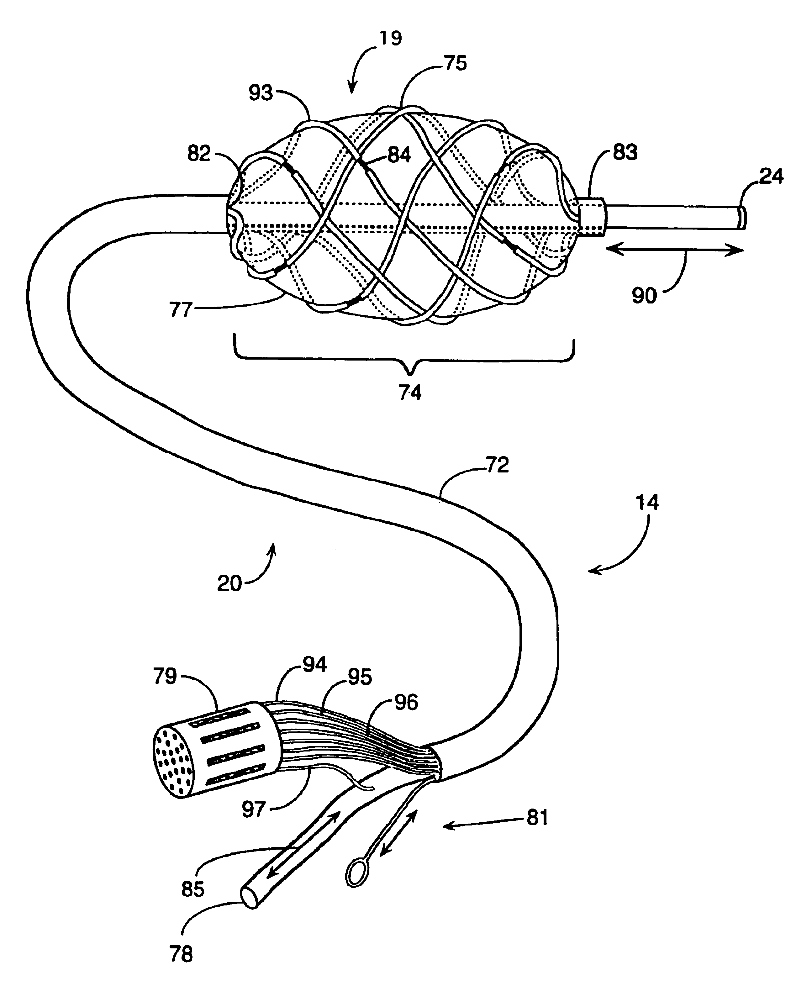
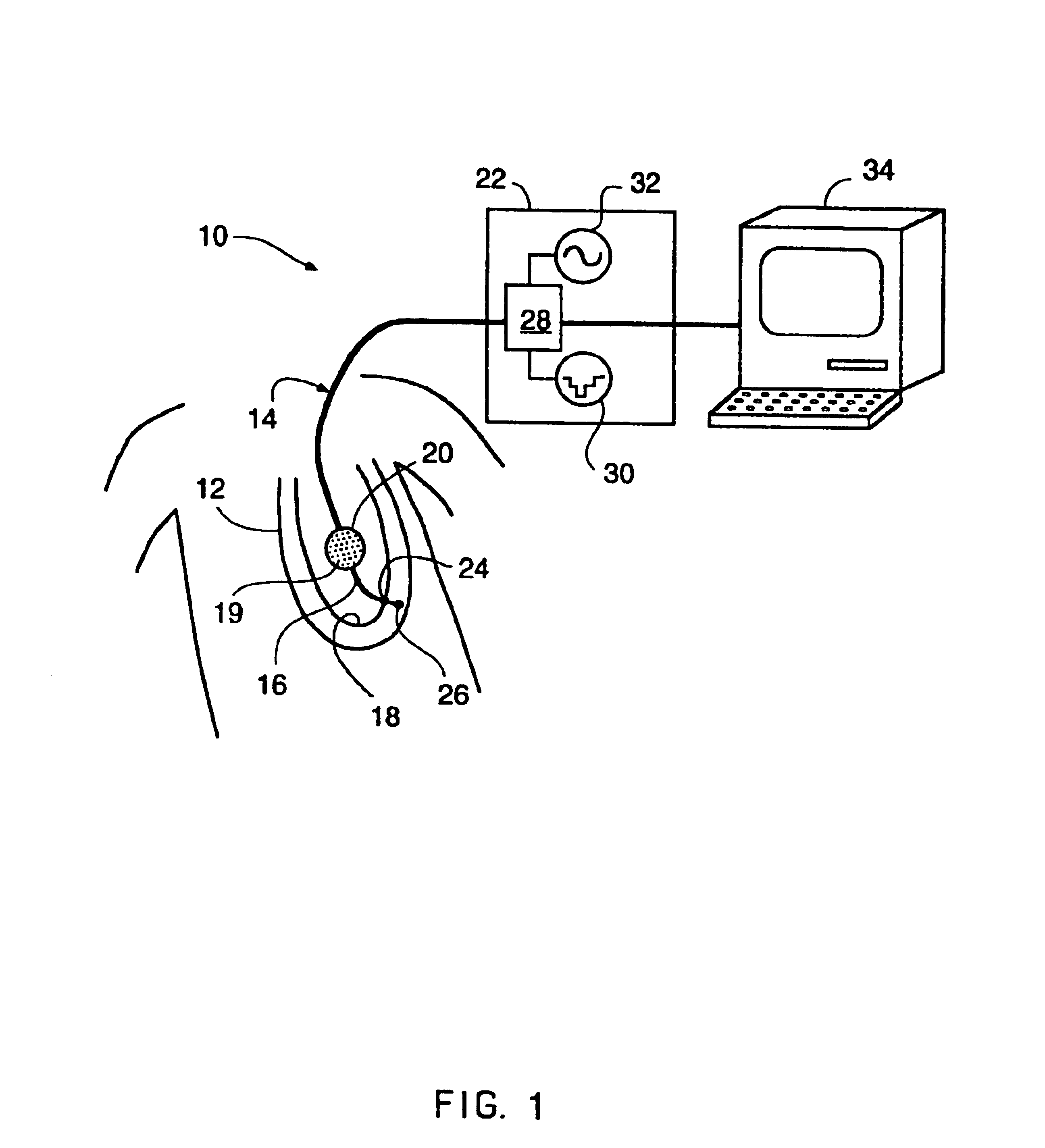
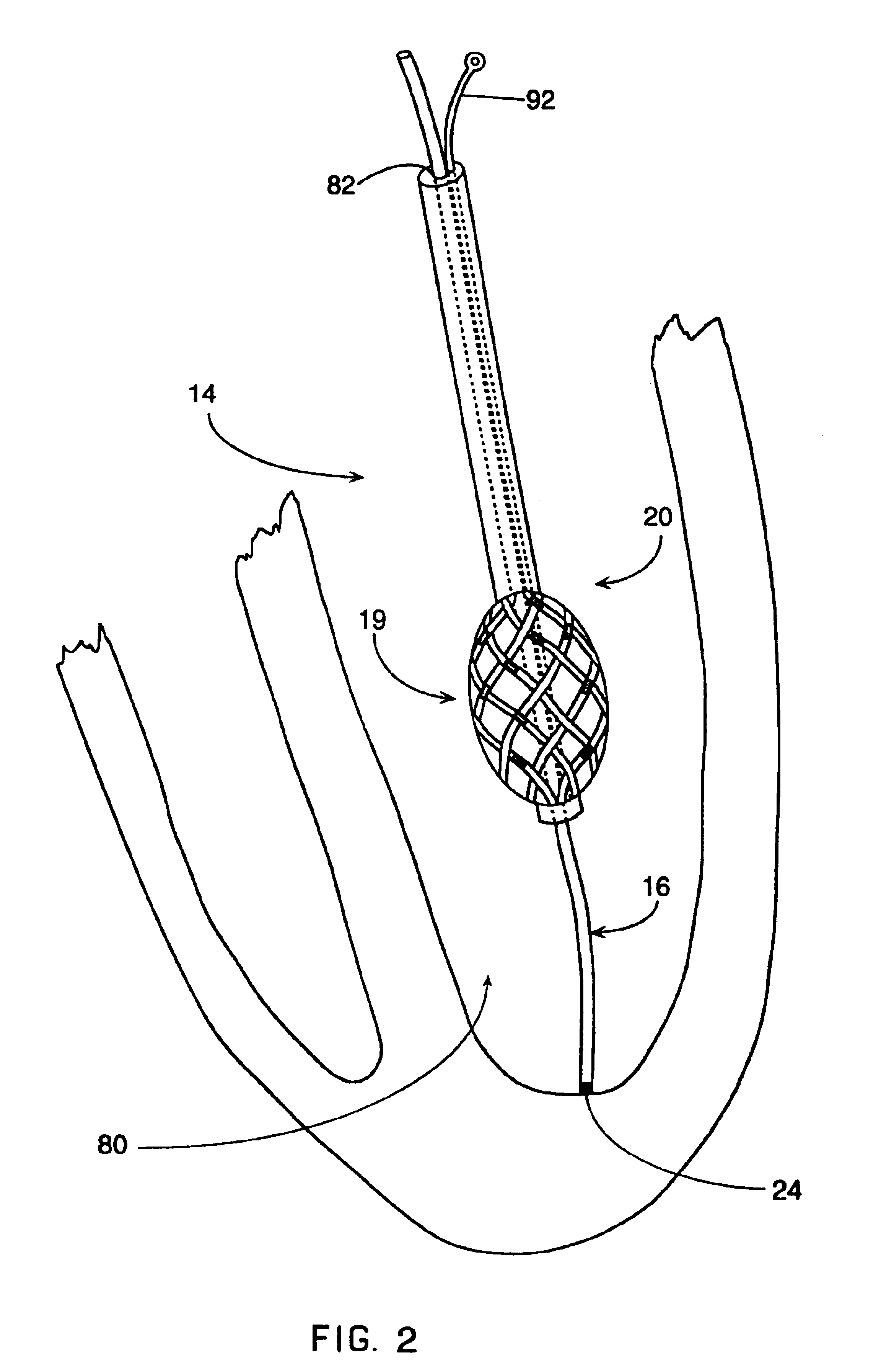
In general, the system of the present invention is used for mapping the electrical activity of the interior surface of a heart chamber 80. The mapping catheter assembly 14 includes a flexible lead body 72 connected to a deformable distal lead body 74. The deformable distal lead body 74 can be formed into a stable space filling geometric shape after introduction into the heart cavity 80. This deformable distal lead body 74 includes an electrode array 19 defining a number of electrode sites. The mapping catheter assembly 14 also includes a reference electrode preferably placed on a reference catheter 16 which passes through a central lumen 82 formed in the flexible lead body 72 and the distal lead body 74. The reference catheter assembly 16 has a distal tip electrode assembly 24 which may be used to probe the heart wall. This distal contact electrode assembly 24 provides a surface electrical reference for calibration. The physical length of the reference catheter 16 taken with the pos...


PUM

PropertyMeasurementUnit
cardiac electrical potentialsaaaaaaaaaa
diameteraaaaaaaaaa
electrical potentialsaaaaaaaaaa

Abstract

A mapping catheter is described to map electric field activity in a heart chamber. The catheter has a first grouping of electrodes positioned so that they are not in contact with the patient's heart. The catheter also having a second set of electrodes positioned in contact with the patient's heart.

Description

The invention discloses the apparatus and technique for forming a three-dimensional electrical map of the interior of a heart chamber, and a related technique for forming a two-dimensional subsurface map at a particular location in the endocardial wall.It is common to measure the electrical potentials present on the interior surface of the heart as a part of an electrophysiologic study of a patient's heart. Typically such measurements are used to form a two-dimensional map of the electrical activity of the heart muscle. An electrophysiologist will use the map to locate centers of ectopic electrical activity occurring within the cardiac tissues. One traditional mapping technique involves a sequence of electrical measurements taken from mobile electrodes inserted into the heart chamber and placed in contact with the surface of the heart. An alternative mapping technique takes essentially simultaneous measurements from a floating electrode array to generate a two-dimensional map of ele...

Claims


Application Information

Patent Timeline
Patent Type & Authority Patents(United States)
IPC IPC(8): A61B5/0408A61B5/042A61B5/0402A61B5/0428A61B5/107A61B5/296A61B5/308A61B18/14A61B18/18A61B18/24A61M25/00A61N1/362A61N1/37
CPCA61B5/04085A61B5/0422A61B5/0538A61B5/1076A61B5/6853A61B5/6858A61B18/1492A61N1/3625A61N1/3702A61B5/042Y10T29/49117A61B5/0428A61B18/18A61B18/1815A61B18/24A61B2018/00214A61B2018/00267A61B2018/00839A61B2560/045A61B2562/0209A61B2562/043A61B2562/046A61B5/283A61B5/282A61B5/30A61B5/287A61B5/308
Inventor BEATTY, GRAYDON ERNESTKAGAN, JONATHANBUDD, JEFFREY ROBERT
Owner ST JUDE MEDICAL ATRIAL FIBRILLATION DIV
Learn More