
Connecting rod structure

Inactive Publication Date: 2004-06-08
MEYER GMBH
View PDF5 Cites 29 Cited by
  • Summary
  • Abstract
  • Description
  • Claims
  • Application Information

AI Technical Summary

Benefits of technology

This solution ensures effective lubrication between the connecting rod and piston, enhancing engine operation and reducing fuel consumption by providing lubrication directly from the oil pump, thus preventing engine breakdowns and conserving energy.

Problems solved by technology

The oil is directly provided by the oil pump, and the connecting rod structure does not construct any oil path to provide lubrication.

Method used


Image

  • Connecting rod structure
  • Connecting rod structure
  • Connecting rod structure

Examples


Embodiment Construction

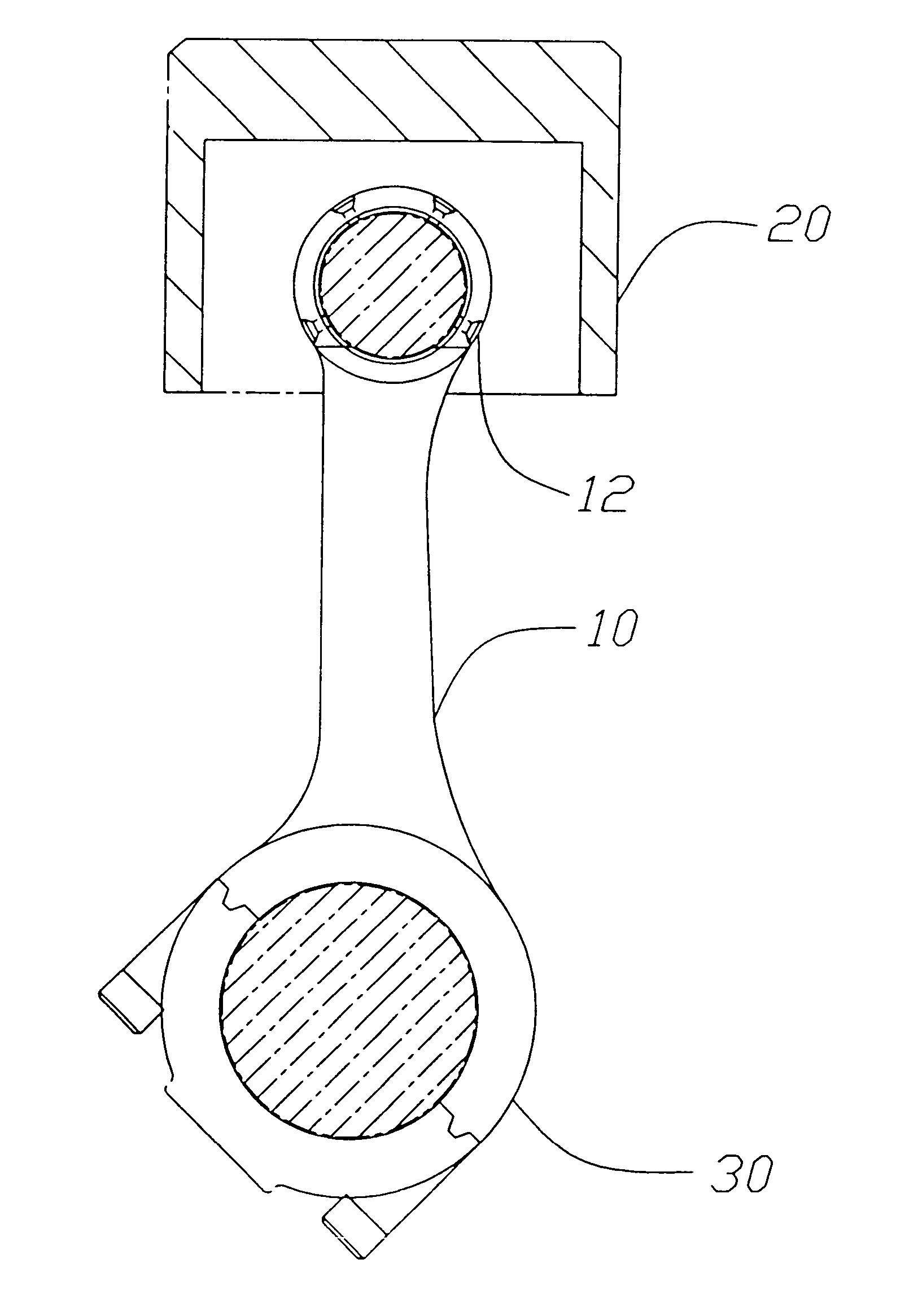
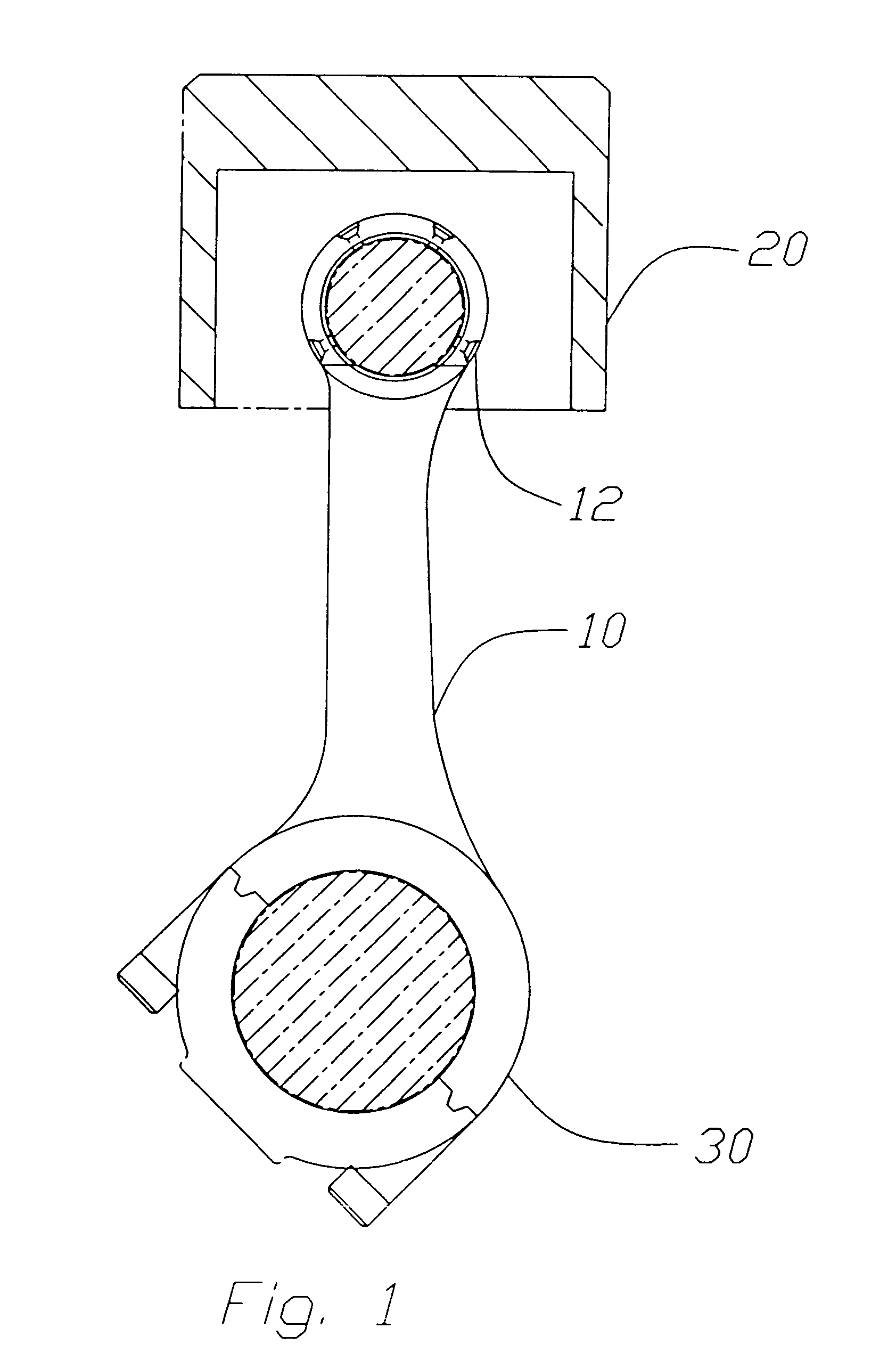
Referring to FIG. 1, the present invention discloses a connecting rod 10 which connects a piston 20 and a crankshaft 30. The connecting rod 10 comprises at least one hole 12 which provides lubrication system to engine. Furthermore, one end of the connecting rod 10 couples to the piston 20 has at least one hole 12 to lubricate. The connecting rod 10 does not design any oil path for lubricating between the connecting rod 10 and the piston 20. According to design of the present invention, the structure of the connecting rod 10 of the present invention provides an effective lubrication system to lubricate between the piston 20 and connecting rod 10.

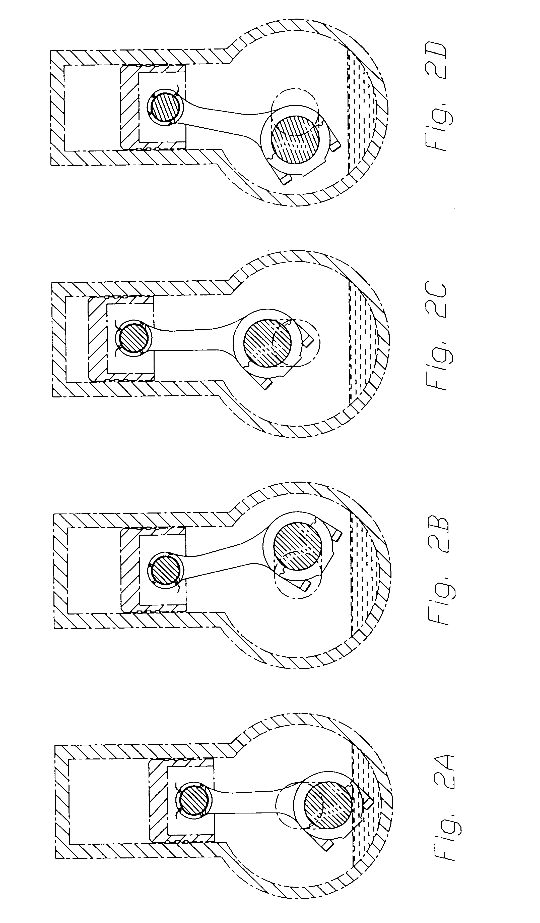
Referring to FIGS. 2A to 2D, the connecting rod of present invention provides the lubrication system in engine operation. In this embodiment discloses four holes of lubrication system between the connecting rod and piston. Referring to FIGS. 2A to 2D, the holes provide oil to lubricate between piston and connecting rod. When the engine begins...


PUM


Abstract

An engine having a connecting rod, a piston and a crankshaft is provided. The connecting rod extends between to connect the piston and the crankshaft. The connecting rod has formed therethrough at least one hole which provides a lubrication path to an interface between the connecting rod and piston conjunction point.

Description

1. Field of InventionThe present invention relates to a lubrication system of engine, more particularity, and to a connecting rod structure which has at least one hole to provide lubricating effect between connecting rod and piston.2. Description of Prior ArtGenerally speaking, most of engine includes a connecting rod, a crankshaft and a piston and provide power to a machine such as car. The state of engine directly effects life of machine and performance so that a way to maintain is mainly lubricant. The lubricant mostly functions describes as following:A. Decreasing of FrictionThe metal surface is perfect smooth, but could create abrasion condition working in long term. The lubricant oil provides each parts of engine to lubricate for decreasing of friction between surfaces of metals.B. Decreasing of Engine TemperatureThe temperature of engine inside is high at 500 to 600.degree.. In this situation, the metal not only expands to create traction but also creates carbon blacks to mak...

Claims


Application Information

Patent Timeline
Patent Type & Authority Patents(United States)
IPC IPC(8): F01M1/06F01M1/08F01M1/00F16C7/02
CPCF01M1/06F16C7/023F01M2001/066F01M2001/086
Inventor ERIKBRANDTZA^EG
Owner MEYER GMBH
Learn More