Physical training apparatus and traction device therefor

a technology of traction device and training apparatus, which is applied in the direction of sport apparatus, frictional force resistor, weight, etc., can solve the problems of rapid wear of the pull cord, marked restriction of training versatility and use, and sharp restriction of the number of exercising persons

Inactive Publication Date: 2004-04-27
KOOPERA
View PDF13 Cites 46 Cited by
  • Summary
  • Abstract
  • Description
  • Claims
  • Application Information

AI Technical Summary

Problems solved by technology

Small machines are also known, which are designed to be transportable, but the training versatility and use of which are markedly restricted.
Training machines which can be folded together and cleared away are also known, the number of exercising persons and training versatility being sharply restricted with these machines.
Moreover, traction devices with pull cords and deflecting rollers are known, in which the pull cord is guided in such a way as to provide oblique pull-cord feed angles along the path to the deflecting rollers, so that it is no longer possible to operate the traction device over a large pivotable angular range or a permanently operative feed of the pull cord to the deflecting rollers can no longer be ensured, since the feed of the pull cord at oblique angles results in increased stresses on the pull cord or the deflecting rollers, thus leading to relatively rapid wear of the pull cord and not being very conducive to long-lasting usefulness.

Method used


Image

  • Physical training apparatus and traction device therefor
  • Physical training apparatus and traction device therefor
  • Physical training apparatus and traction device therefor

Examples


Embodiment Construction

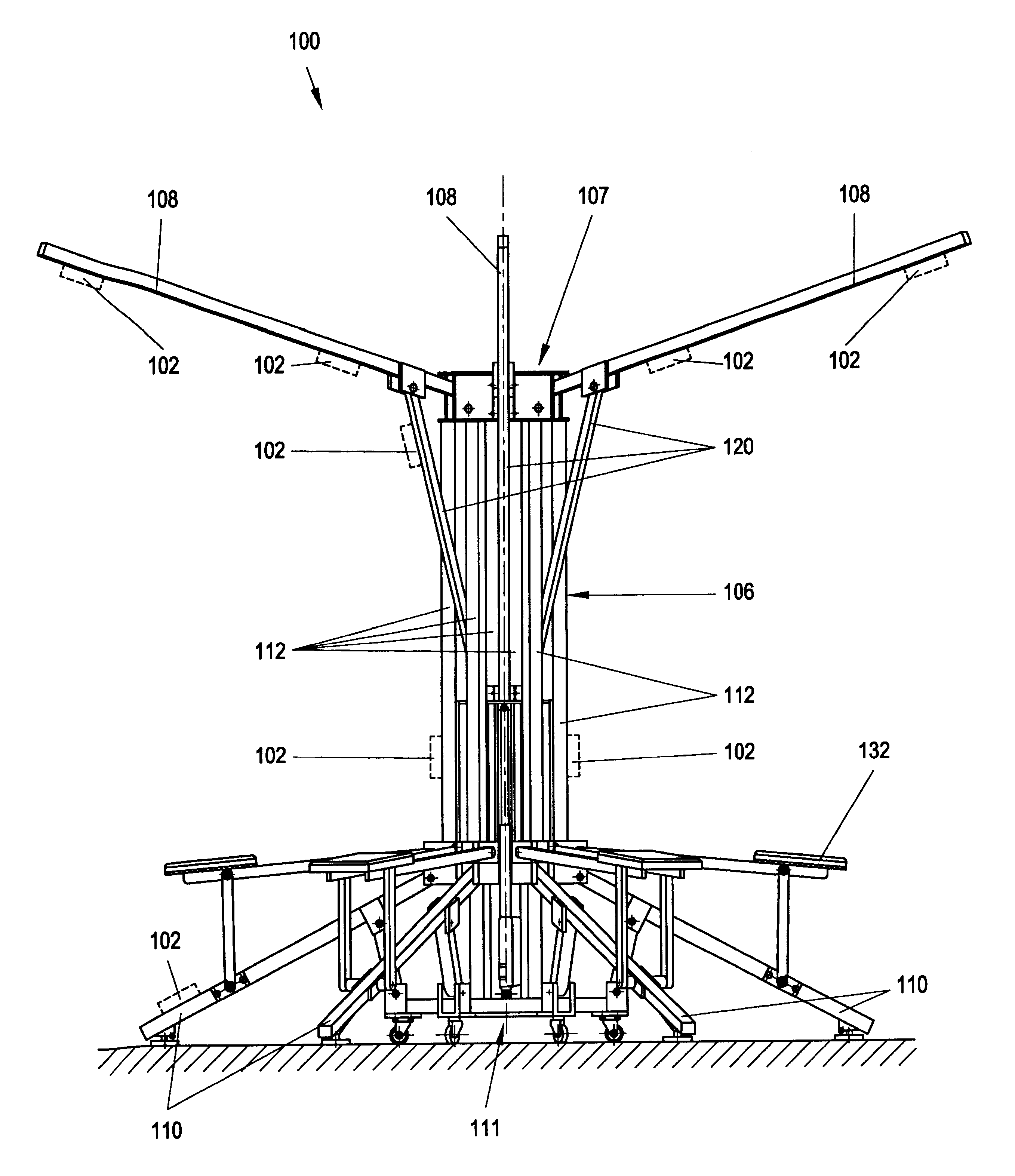
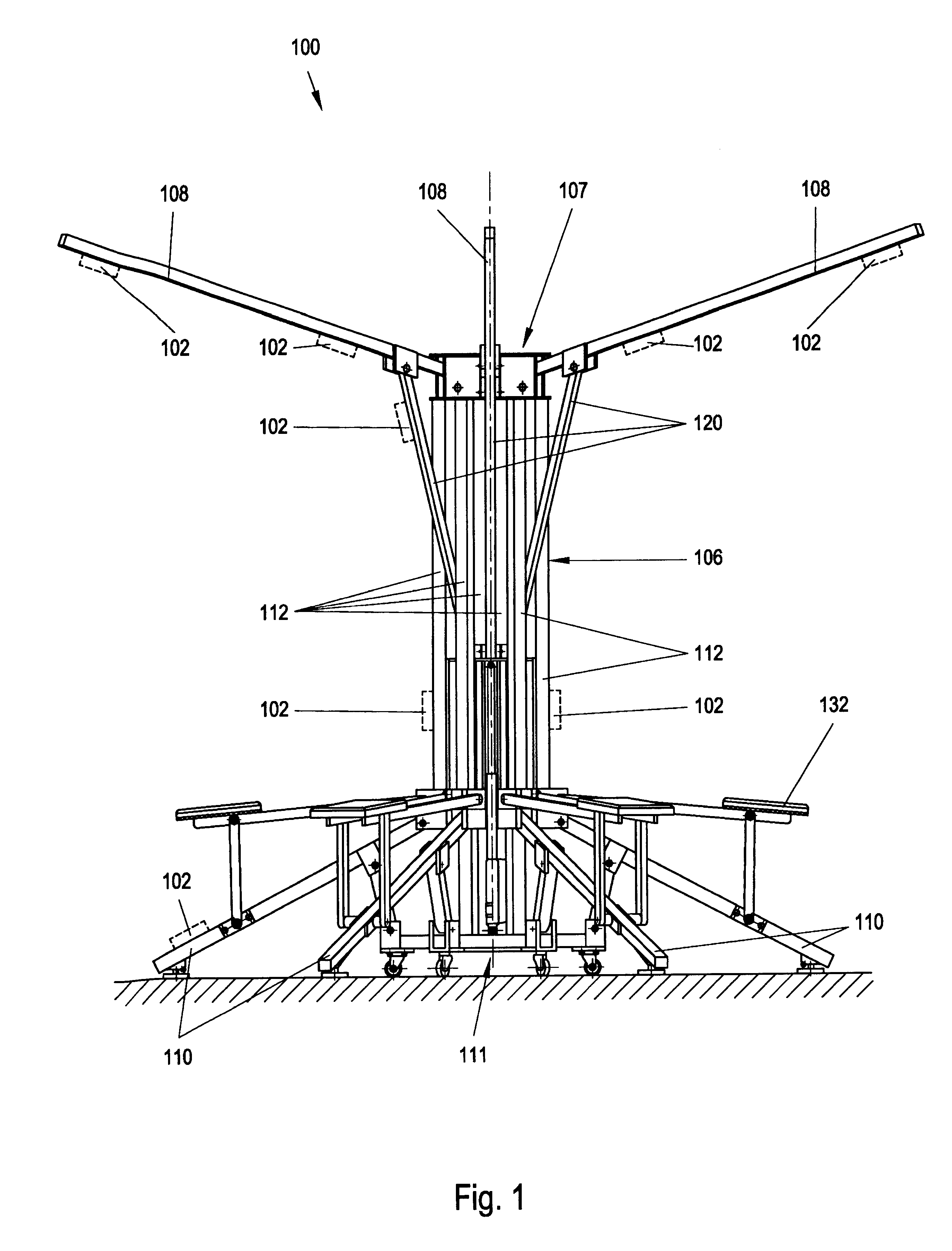
A training machine 100 possesses a carrying device 106, which consists of vertically arranged profile bars 112 with mortises 125 which are continuous in the longitudinal direction, altogether six profile bars 112 being arranged so as to be offset, each at a circumferential angle of 60.degree., along the contour of a circle, as seen in a top view. The lower end of the profile bars 112 is connected to a base unit 111 which is mounted on rollers 117. The upper end of the profile bars 112 is connected to a head unit 107. Fastened below the head unit 107 is an accumulator 115 which supplies current to a linear drive 130 arranged on the base unit 111 and having an extensible push rod 131. The push rod 131 is illustrated in the extended state in FIG. 10. Connected to the end of the push rod 131 is a guide unit 118 which is designed as a guide plate within the carrying device 106. At the edge of the guide unit 118 there are guide bars 119 which point downwards, offset at a circumferential a...


PUM


Abstract

A training machine (100) for the physical training of persons, having, arranged on it, traction devices (102) with pull cords and deflecting rollers, is characterized bya central carrying device (106) displaceably mounted as a unit,traction-device holding rods (108) articulated in the upper region of the carrying device (106),which are present circumferentially around the carrying device (106), at least in regions, in a predeterminable pattern,which are designed to be capable of being unfolded and folded up, as required, andwhich, in the unfolded state, delimit the respective training area available to a person for training purposes,floor supporting profiles (110) articulated in the lower region on the carrying device (106),which are present circumferentially around the carrying device (106) in a predeterminable pattern,which are designed to be capable of being unfolded and folded up, as required, andwhich, in the unfolded state, are supported on a standing floor and ensure the stability of the training machine (100),the traction devices (102) being arranged on the traction-device holding rods (108) and / or the floor supporting profiles (110) and / or the carrying device (106).

Description

The present invention relates to a training machine for the physical training of persons, having, arranged on it, traction devices with a pull cord and deflecting rollers.PRIOR ARTKnown training machines are distinguished in that they are of stationary design and require a certain amount of space. Small machines are also known, which are designed to be transportable, but the training versatility and use of which are markedly restricted. Training machines which can be folded together and cleared away are also known, the number of exercising persons and training versatility being sharply restricted with these machines.In order to implement various training methods in the aerobic area of a fitness studio, so-called "steppers" 1 are used, which are illustrated diagrammatically in FIG. 2 in a group of exercising persons 5. The steppers 1 possess two laterally arranged rubber pull grips 2, 3 which are grasped manually by the exercising persons 5 and can be pulled out. These rubber pull gr...

Claims


Application Information

Patent Timeline
IPC IPC(8): A63B21/062A63B21/06A63B23/00A63B21/00A63B71/02A63B23/035A63B21/16
CPCA63B21/00A63B21/062A63B21/154A63B23/00A63B21/1434A63B2021/0614A63B2071/025A63B2210/56A63B2225/10A63B2225/105A63B21/0628A63B21/0626A63B21/4017
Inventor BEUTEL, GUNTHER
Owner KOOPERA
Why Eureka
Try Eureka