
Method and an electronic apparatus for positioning a cursor on a display

a technology of electronic equipment and display, applied in the direction of instruments, computing, electric digital data processing, etc., can solve the problems of difficult user-friendly input, noisy output signals of pointing devices, spurious or rapidly changing information,

Inactive Publication Date: 2003-11-18
TELEFON AB LM ERICSSON (PUBL)
View PDF7 Cites 19 Cited by
  • Summary
  • Abstract
  • Description
  • Claims
  • Application Information

AI Technical Summary

Problems solved by technology

In these situations, the environment cannot be expected to be as stable and troublefree as in the above case.
On the contrary, the output signals from the pointing device are likely to be noisy and contain spurious or rapidly varying information, due to trembling of the user's hand or finger, unexpected external influence, rapid and temporary variations in speed or direction in the user input, etc.
Consequently, particularly for portable and miniaturized equipment, it may be difficult for the user to provide an accurate input on the pointing device, which obviously may affect the accuracy of the cursor navigation undesiredly.
This generally makes a conventional force joystick frustrating to use, since when the joystick is actuated to its maximum extent, the cursor tends to move across the display at a speed, which is faster than the eye can follow.
In turn, this often causes the user to overshoot the target point on the display, wherein the user will have to make additional joystick corrections in order to recover from the overshoot.
A high level of noise or a large amount of rapid unintentional directional variations will jeopardize a steady cursor course on the display and will make it difficult to navigate properly between different targets on the display.
Presently, it appears that this problem is particularly pronounced for pointing devices of subclasses two and three above, i.e. force-type joysticks, touch pads, fingerprint detectors, etc.

Method used


Image

  • Method and an electronic apparatus for positioning a cursor on a display
  • Method and an electronic apparatus for positioning a cursor on a display
  • Method and an electronic apparatus for positioning a cursor on a display

Examples


Embodiment Construction

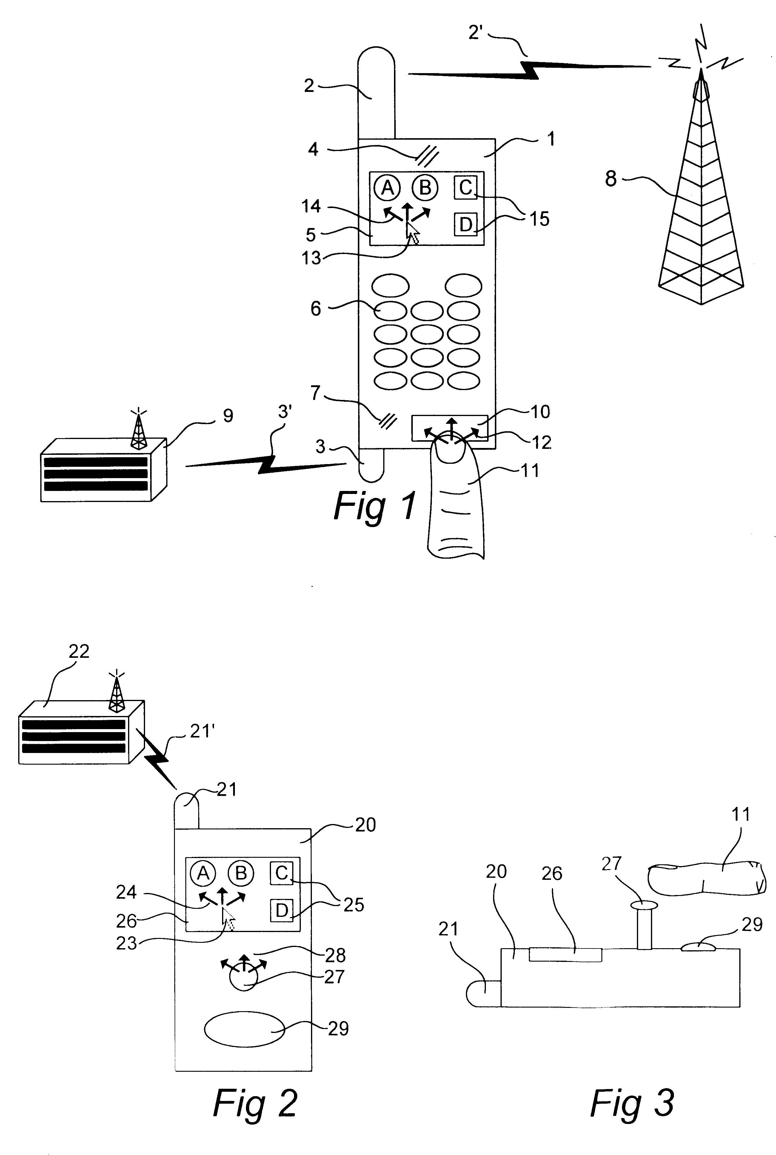
FIG. 1 illustrates an electronic apparatus in the form of a mobile telephone 1. FIG. 2 shows an electronic apparatus 20 for remote financial transactions, e.g. wireless payment. The mobile telephone 1 of FIG. 1 and the electronic payment device 20 of FIG. 2 are provided as two examples of an electronic apparatus, in which the present invention may be applied.

As shown in FIG. 1, the mobile telephone 1 comprises a first antenna 2, which is adapted to establish and maintain a first radio link 2' to a base station 8 in a mobile telecommunications system, such as GSM ("Global System for Mobile communications"). The mobile telephone 1 also has a second antenna 3, which is used for communicating with a remote device 9 over a second radio link 3'. The second antenna 3 may for instance be adapted for Bluetooth.RTM. or another kind of short-range supplementary data communication, e.g. on the 2.4 GHz ISM band ("Industrial, Scientific and Medical"). Bluetooth is a registered trademark in the na...


PUM


Abstract

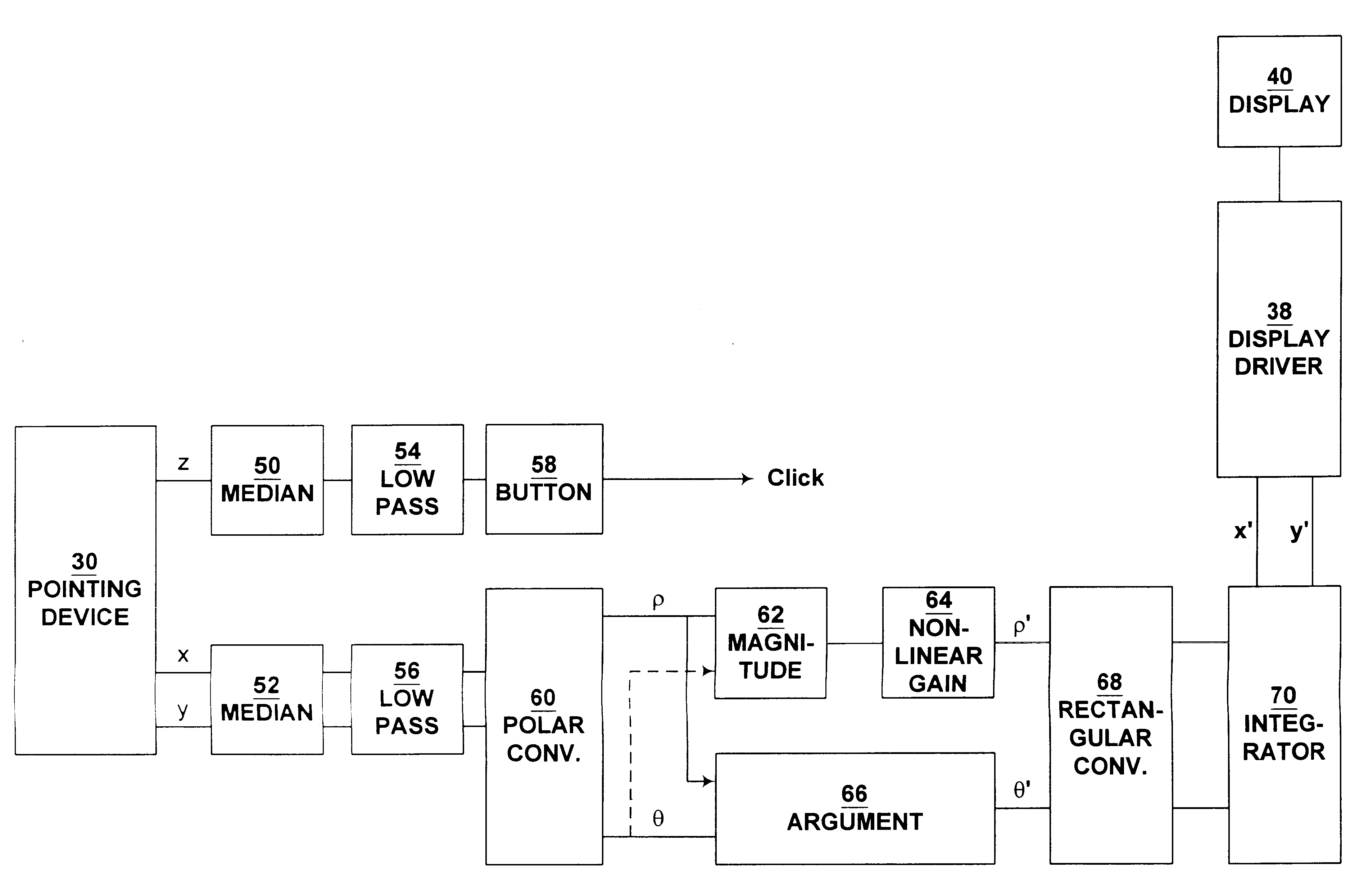
A cursor (13) is positioned on a display (5) in response to a user input (12) on a pointing device (10). The user input, which represents a desired cursor movement (14) on the display, is converted to time varying magnitude and argument components in polar space. The magnitude component is processed so as to control a speed of movement of the cursor on the display. Separately from this, the argument component is processed so as to suppress rapid angular variations in the movement of the cursor on the display.

Description

The present invention relates to a method and an electronic apparatus for positioning a cursor on a display in response to a user input on a pointing device, where the user input represents a desired cursor movement on the display.PRIOR ARTA wide variety of pointing devices have been proposed and used to implement user control of a cursor on a graphical display screen. The simplest form of pointing device is a set of navigation keys on a keypad, normally implemented as "arrow keys", which represent discrete cursor movements upwards, downwards, to the left and to the right on the screen. The present invention is not particularly related to such discrete pointing devices.The other main class of pointing devices is continuous (analog) devices, where the user controls the cursor position in a continuous manner by varying a physical input to the pointing device. A first subclass of continuous pointing devices comprises positional (movable) joysticks, mouse controls and trackball controls...

Claims


Application Information

Patent Timeline
Patent Type & Authority Patents(United States)
IPC IPC(8): G06F3/023G06F3/033G06F3/038G06F3/0489
CPCG06F3/04892G06F3/038
Inventor PHILIPSON
Owner TELEFON AB LM ERICSSON (PUBL)
Learn More