
Touch panel device

a technology of touch panel and device body, which is applied in the field of touch panel devices, can solve the problems of limiting detection precision and increasing the size of the devi

Inactive Publication Date: 2003-10-14
PIONEER CORP +1
View PDF4 Cites 153 Cited by
  • Summary
  • Abstract
  • Description
  • Claims
  • Application Information

AI Technical Summary

Problems solved by technology

However, the ultrasonic surface acoustic wave system touch panel device in the conventional art has problems such that, as shown in FIG. 25, the transmitter-side reflection array and the receiver-side reflection array must be arranged on four sides of the touch panel respectively and in addition, in order to reduce the detection error by increasing the detection precision of the touch position, the size of the device is increased and the detection precision has a limit since acoustic transmitter portions and receiver portions must set finely in the transmitter-side reflection array and the receiver-side reflection array respectively.
Therefore, if this touch panel device is fitted to the plasma display panel (PDP), for example, there is such a possibility that the vibration generated in the touch panel 1 by driving the PDP is sensed as the noise and thus the error is caused in the detection result.

Method used


Image

  • Touch panel device
  • Touch panel device
  • Touch panel device

Examples


Embodiment Construction

Preferred embodiments of the present invention will be explained with reference to the accompanying drawings hereinafter.

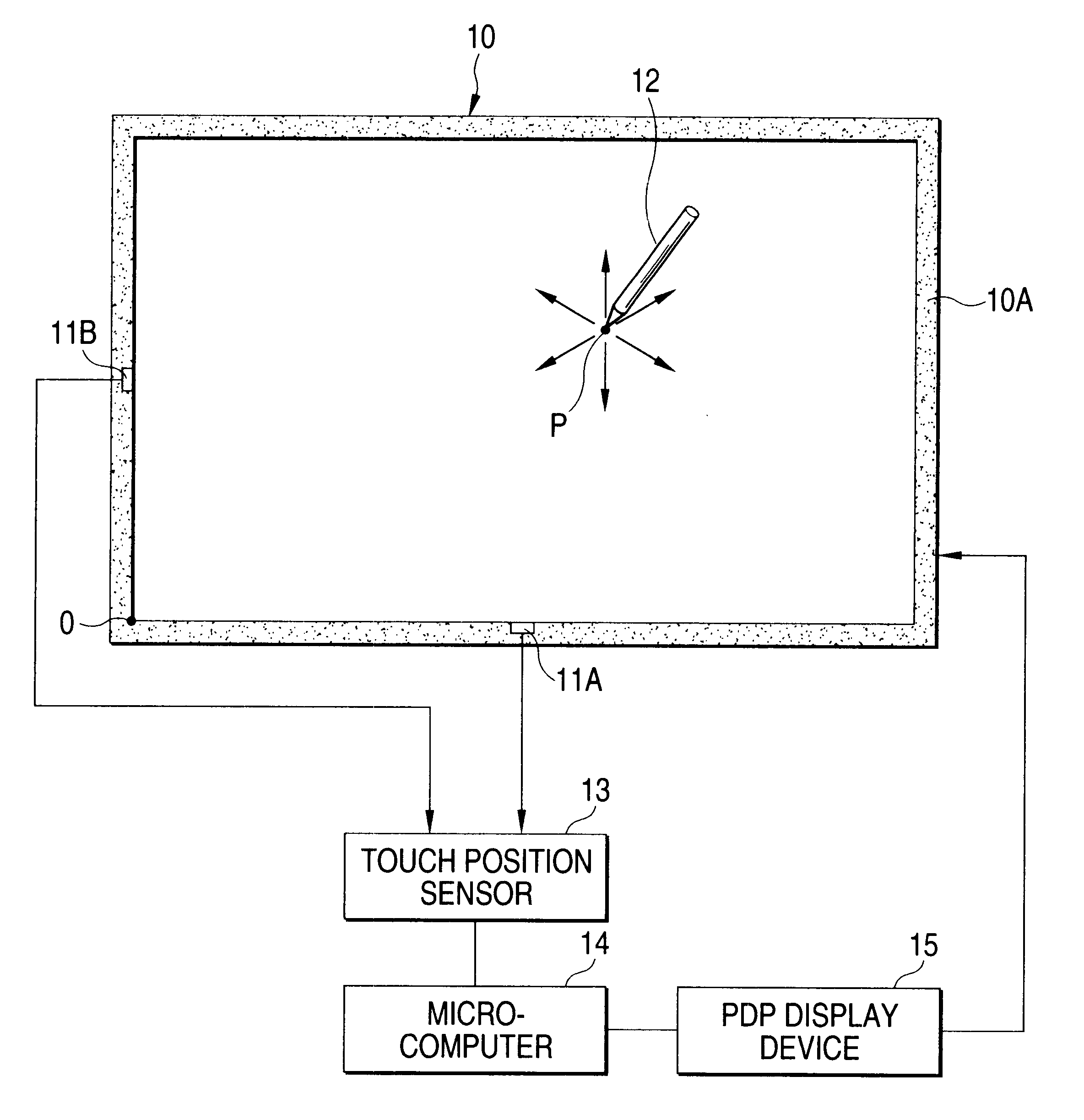
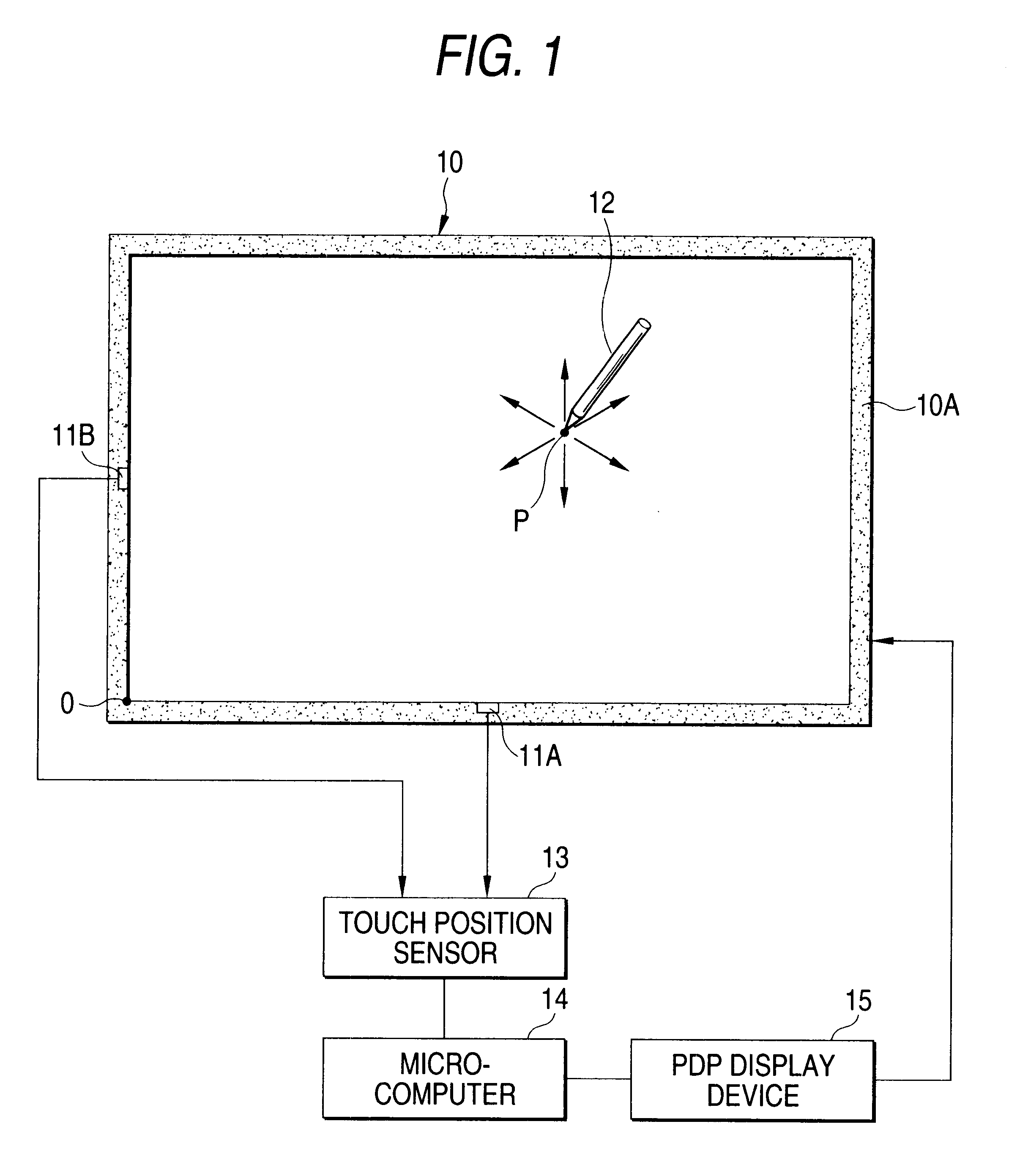
FIG. 1 is a view showing a configuration of a first example in the embodiment of the touch panel device according to the present invention.

In the following, explanation will be made while taking as an example the case where the touch panel device is fitted in front of the plasma display panel (abbreviated as "PDP" hereinafter). But the touch panel device may be fitted to the white board and the tablet in addition to PDP.

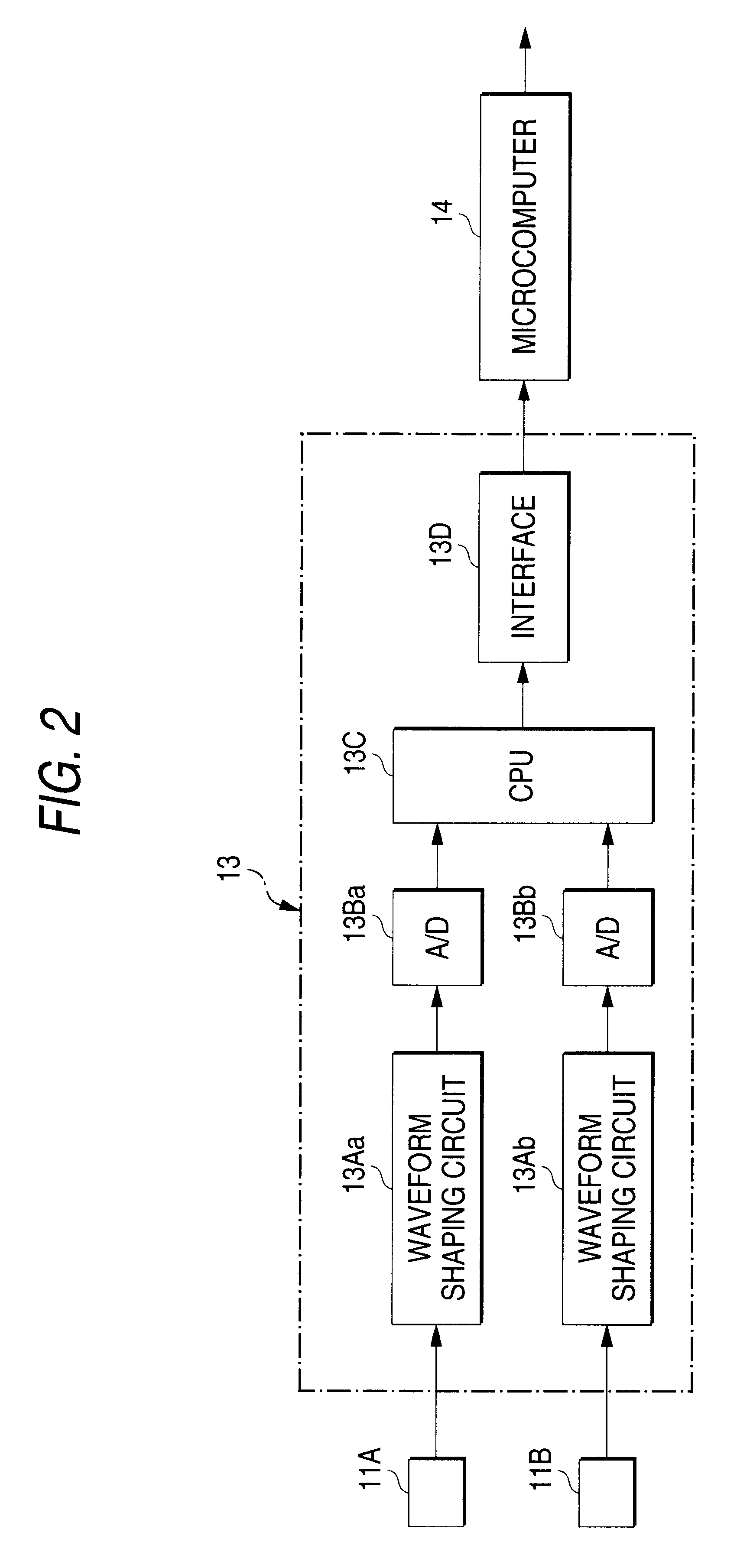
In FIG. 1, a front glass substrate of the PDP constitutes a touch panel 10 of the touch panel device. The touch panel device comprises two microphones 11A and 11B provided to a center position of a lower edge portion and a center position of a left-hand edge portion of a front surface of the touch panel 10 respectively; an input pen 12 built in a ultrasonic oscillator described later; and a touch position sensor 13 that is connected to two micropho...


PUM


Abstract

There are provided microphones <HIL><PDAT>11< / BOLD><PDAT>A, <HIL><PDAT>11< / BOLD><PDAT>B arranged at least any two different locations of edge portions of a touch panel <HIL><PDAT>10, < / BOLD><PDAT>for sensing a ultrasonic signal propagated through a space, an input pen <HIL><PDAT>12 < / BOLD><PDAT>containing a piezoelectric loudspeaker <HIL><PDAT>12< / BOLD><PDAT>G, for oscillating a ultrasonic wave that is output from the piezoelectric loudspeaker <HIL><PDAT>12< / BOLD><PDAT>G, and a touch position sensor <HIL><PDAT>13 < / BOLD><PDAT>for calculating a coordinate of a touch position P by calculating distances between the microphones <HIL><PDAT>11< / BOLD><PDAT>A, <HIL><PDAT>11< / BOLD><PDAT>B and the touch position P of the input pen <HIL><PDAT>12 < / BOLD><PDAT>on the touch panel <HIL><PDAT>10 < / BOLD><PDAT>based on the ultrasonic wave sensed by the microphones <HIL><PDAT>11< / BOLD><PDAT>A, <HIL><PDAT>11< / BOLD><PDAT>B, whereby the microphones <HIL><PDAT>11< / BOLD><PDAT>A, <HIL><PDAT>11< / BOLD><PDAT>B have a sound collecting directivity characteristic in response to fitted positions of the edge portions of the touch panel <HIL><PDAT>10. < / BOLD>< / PTEXT>

Description

1. Field of the InventionThe present invention relates to a touch panel device in which information are input by an input pen onto a touch panel that is provided in front of a flat display such as a plasma display panel, etc.2. Description of the Related ArtIn recent years, the touch panel device has been spread as the inputting means for various information processing devices.This touch panel device senses a coordinate of a touch position on the touch panel, and inputs various information into the information processing device in response to the touch position. Various systems have been proposed.Out of the touch panel devices, there is the ultrasonic surface acoustic wave system that senses the coordinate of the touch position on the touch panel by utilizing the ultrasonic wave.FIG. 25 is a schematic view showing the touch panel device in the conventional art utilizing the ultrasonic surface acoustic wave system.In FIG. 25, the touch panel device comprises an X-side reflection arra...

Claims


Application Information

Patent Timeline
IPC IPC(8): G09G5/00G06F3/033G06F3/043G06F3/041
CPCG06F3/0433G06F3/03545
Inventor MATSUMOTO, KANYANAKAZONO, JIRO
Owner PIONEER CORP
Learn More