
Motor vehicle seat

Inactive Publication Date: 2003-08-12
BERTRAND FAURE SITZTECHN
View PDF21 Cites 3 Cited by
  • Summary
  • Abstract
  • Description
  • Claims
  • Application Information

AI Technical Summary

Benefits of technology

Thus, a motor vehicle seat according to the present invention comprises an underlying framework including a backrest framework

Problems solved by technology

In situations that deviate from design conditions, the seat may be designed so as to be too rigid, with the result that in the event of a crash, the user is exposed to accelerations that are too great.
If, on the other hand, the motor vehicle seat is designed so as to be too soft, when conditions deviate from the conditions of the design, the danger of injury for the user as a result of insufficient holding strength in the construction of the seat becomes increased.

Method used


Image

  • Motor vehicle seat
  • Motor vehicle seat
  • Motor vehicle seat

Examples


Embodiment Construction

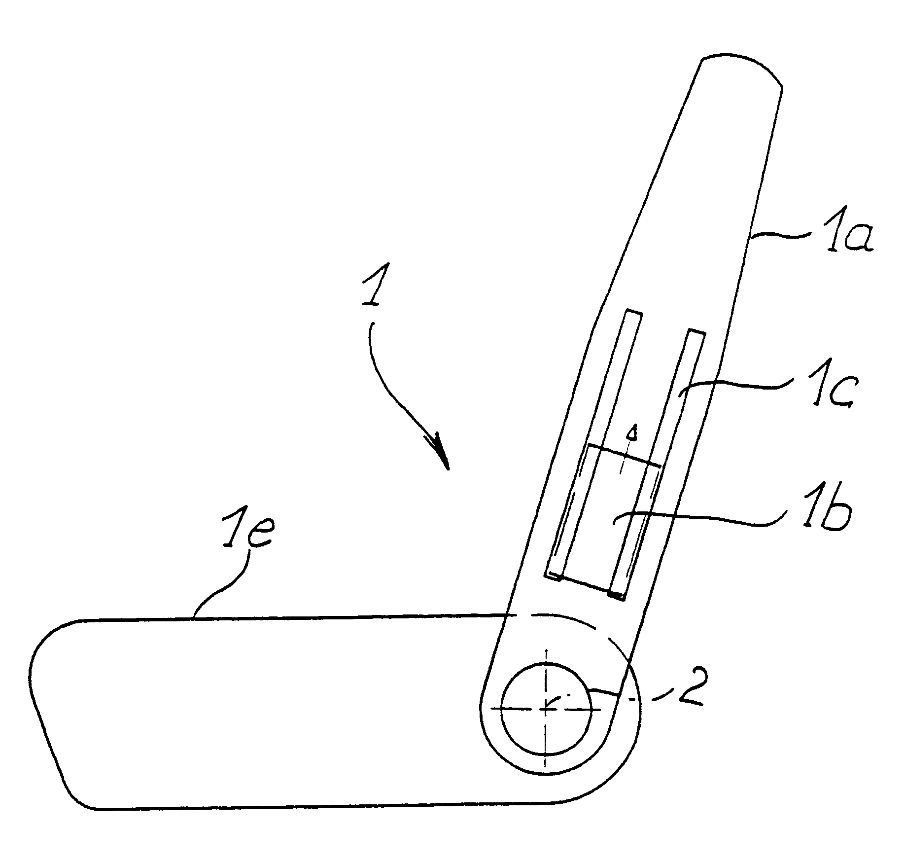
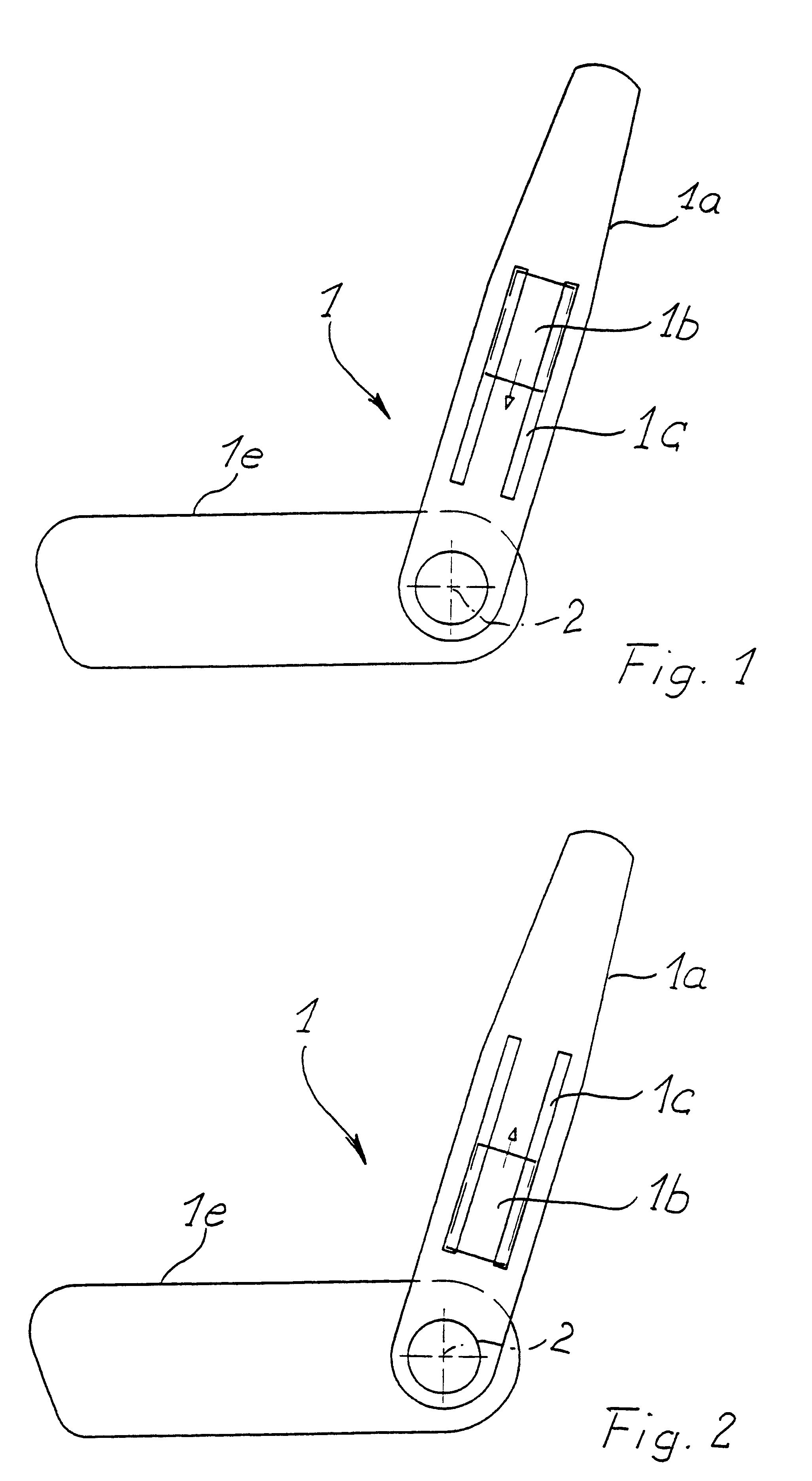
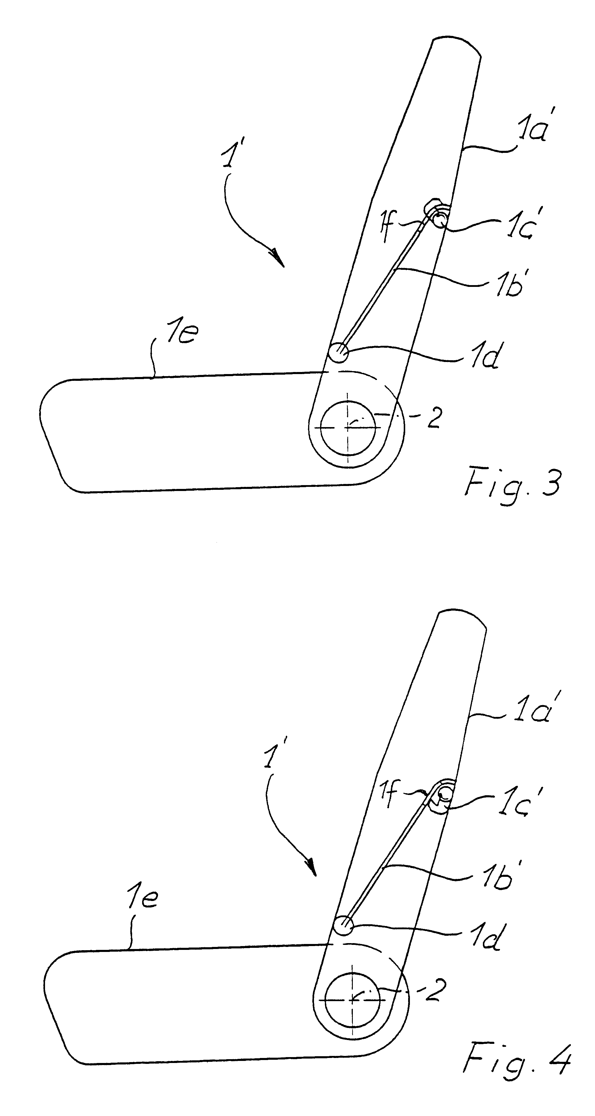
In all the following embodiments, the motor vehicle seat has an underlying framework 1 that comprises a backrest framework la and a seat framework 1e. The various embodiments are distinguished by the nature and attachment of the reinforcement or stiffening elements which may be attached to the backrest framework 1a.

In the case of the embodiment shown in FIGS. 1 and 2, a plate-shaped reinforcement or stiffening element that imports rigidity, 1b, is provided, whose distance from the axis of inclination 2 may be shifted. The plate-shaped reinforcement element or stiffening element 1b is moved between guide tracks 1c that are parallel to one another and firmly connected to the backrest framework 1a, or are embodied with it so as to form a single piece.

In FIG. 1, the plate-shaped reinforcement element 1b is moved upwardly in such a way that it is positioned at the greatest distance from the axis of inclination 2. In this upwardly shifted position of the reinforcement element 1b, the rigi...


PUM


Abstract

A motor vehicle seat comprises an underlying framework and reinforcement or stiffening elements which are positioned in adjustable manner relative to the underlying framework to control the firmness of the seat framework in accordance with the user's characteristics and driving conditions.

Description

BACKGROUND OF THE INVENTIONThe invention relates to a motor vehicle seat with a seat frame.Known motor vehicle seats are designed, in terms of their firmness, in accordance with the automobile industry's testing conditions, for a dummy that is intended to be representative of 95% of the actual users. In the process, if possible, design takes several driving and accident situations into account. In situations that deviate from design conditions, the seat may be designed so as to be too rigid, with the result that in the event of a crash, the user is exposed to accelerations that are too great. If, on the other hand, the motor vehicle seat is designed so as to be too soft, when conditions deviate from the conditions of the design, the danger of injury for the user as a result of insufficient holding strength in the construction of the seat becomes increased.SUMMARY OF THE INVENTIONBased on the state of the art as described above, it is an objective of the present invention to control ...

Claims


Application Information

Patent Timeline
IPC IPC(8): B60N2/68B60N2/90
CPCB60N2/68
Inventor BROCKMAN, JORGMONNICH, THOMASPERNER, RALFSCHNEIDER, THOMASVOLMAR, KATRIN
Owner BERTRAND FAURE SITZTECHN
Learn More