Leverage-release type silent wrench structure

Inactive Publication Date: 2003-07-22
KUO WEN JIN +1
View PDF4 Cites 10 Cited by
  • Summary
  • Abstract
  • Description
  • Claims
  • Application Information

AI Technical Summary

Benefits of technology

The primary objective of the invention herein is to provide a leverage-release type silent wrench structure that is of simple assembly, noiseless in operation, higher in torque, performance enhancing, and of prolonged service life, wherein when the present invention is utilized on a loose work object, the work object is not affected by drag-induced rotation in the opposite direction as the wrench is pulled back in the disengaged state and, furthermore, in environments of limited angle, the invention herein remains capable of efficiently rotating work objects because it is not impaired by application environment or work object loosening and tightening constraints.
Given the said structure, pulling the said torsion handle with the linkage component serving as the center point of the said torsion handle causes its clutch block to move against the said ratchet wheel such that the toothed surface enmeshes the ratchet wheel, enabling the said torsion handle to initiate the rotation of the said ratchet wheel and thereby rotate a work object; pulling the torsion handle in the opposite direction causes the separation of the toothed surface of the clutch block from the ratchet wheel, enabling the said torsion handle to be rotated back to its initial starting position in a disengaged state around the said linkage component at the center point.

Problems solved by technology

The said solid handle-type ratchet wrench utilizes numerous structural components, its assembly is intricate and tedious, and the quantity of enmeshed teeth between the pawl and the ratchet wheel is comparatively low, resulting in reduced torque.
Furthermore, when the wrench is rotated in the disengaged state, friction between the pawl and the ratchet wheel produces an intense clicking noise and silent operation is not possible.

Method used


Image

  • Leverage-release type silent wrench structure
  • Leverage-release type silent wrench structure
  • Leverage-release type silent wrench structure

Examples


Embodiment Construction

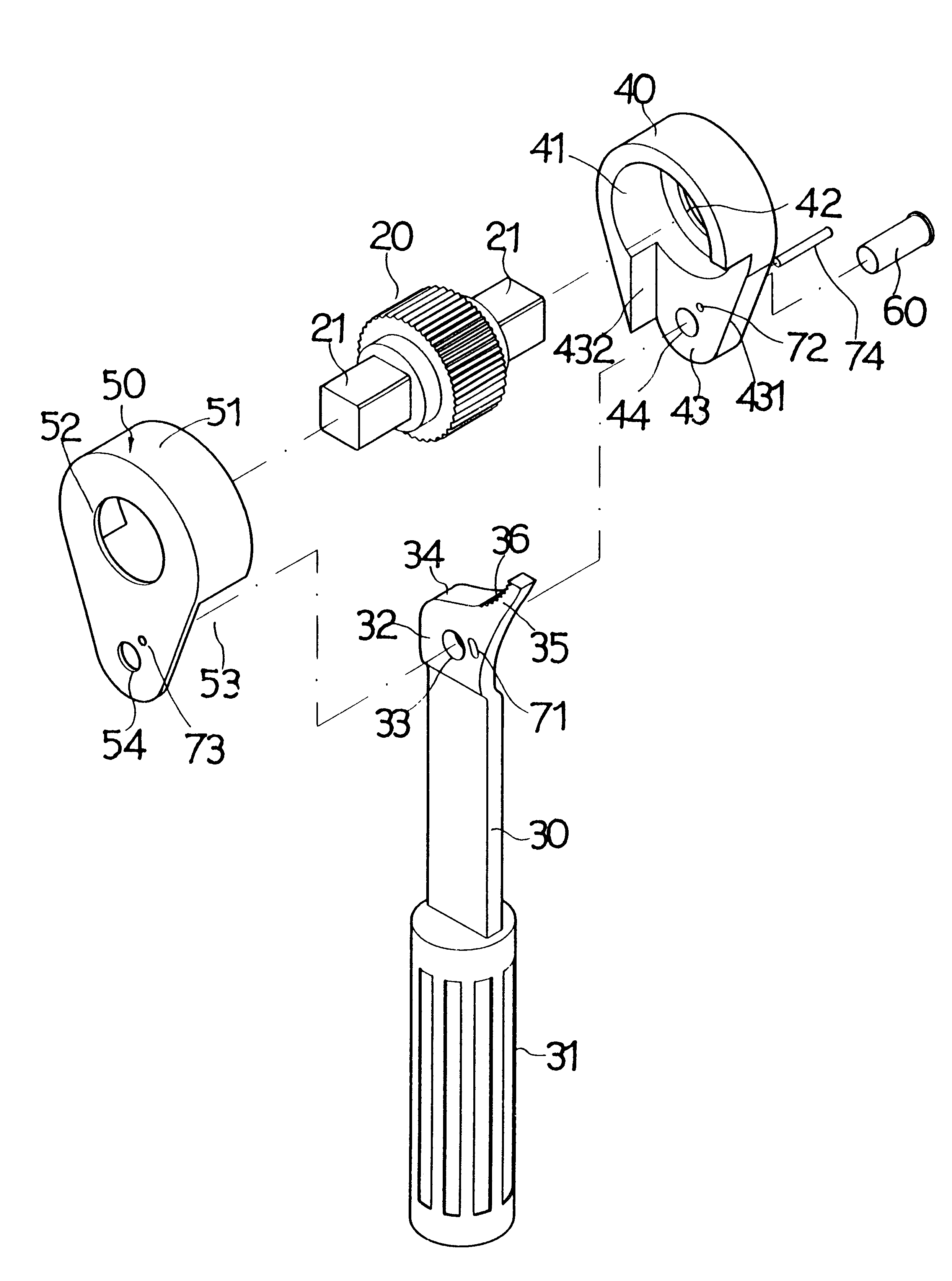
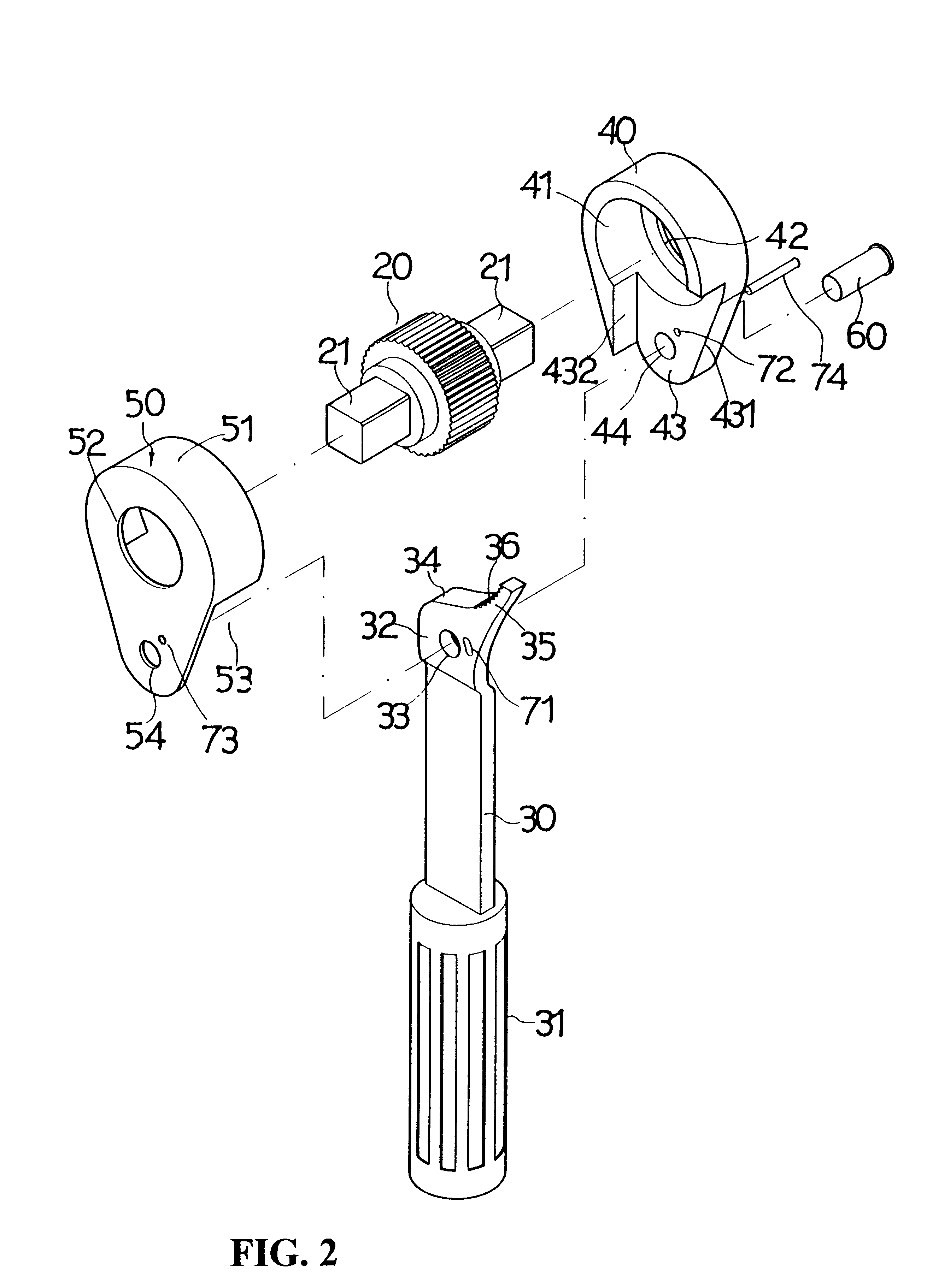
Referring to FIG. 2, FIG. 3, and FIG. 4, the leverage-release silent wrench structure of the invention herein is comprised of:

A ratchet wheel 20; the said ratchet wheel 20 having a tool end at its center and, as indicated in FIG. 2, the tool end consists of a drive tip 21 extending from two sides or, as indicated in FIG. 7, a six-point hex socket 22.

A torsion handle 30 at the lower extent of the said ratchet wheel 20 with a grip 31 sleeved over one end that provides for manual grasping the by user, the other end consisting of a hinge section 32 extending in a curve towards the side of the handle having a pivot hole 33 in the center, a shoulder section 34 along the top edge utilized to support the said ratchet wheel 20, a clutch block 35 curving upward from one side of the said shoulder section 34, and a contoured toothed surface 36 disposed along the arc-shaped inner side of the said clutch block 35 that engages the said ratchet wheel 20.

A mounting base 40 consisting of an inverted ...


PUM


Abstract

A leverage-release type silent wrench structure comprised of a ratchet wheel and a torsion handle having a hinge section at one end that is situated next to the ratchet wheel. A clutch block curves upward from one side of the hinge section and a toothed surface consisting of a plurality of teeth is disposed along the arc-shaped inner side of the clutch block that provides for enmeshment with the ratchet wheel. A mounting base and a protective cover in an aligned arrangement accommodate the positioning of the ratchet wheel and the hinge section of the torsion handle within them. A linkage component pivotably conjoins the mounting base, the protective cover, and the hinge section of the torsion handle and, furthermore, such that the linkage component serves as the center point of rotation of the torsion handle. Pulling the torsion handle causes its clutch block to move against the ratchet wheel such that the toothed surface enmeshes the ratchet wheel, enabling the torsion handle to initiate the rotation of the ratchet wheel and thereby rotate a work object. Pulling the torsion handle in the opposite direction causes the separation of the toothed surface of the clutch block from the ratchet wheel, enabling the torsion handle to be rotated back to its initial starting position in a disengaged state around the linkage component at the center point.

Description

BACKGROUND OF THE INVENTION1) Field of the InventionThe invention herein relates to a wrench tools, specifically a leverage-release type silent wrench structure.2) Description of the Prior ArtIn a conventional ratchet wrench, referring to the structure in FIG. 1, a ratchet wheel is contained in the working end of the wrench, a ball bearing and a spring push against the bottom of a pawl such that one of its corners engage the ratchet wheel, and the pawl is controlled by a toggling lever. The said ratchet wheel is mounted in the working end of the wrench by C-shaped circlips and an upper and lower mounting piece each fastened with two screws. To operate, the user moves the toggling lever to selectively engage one of the pawl corners with the ratchet wheel such that pulling the said wrench in one direction rotates the said ratchet wheel and the work object, while pulling the wrench in the opposite direction disengages the pawl and disables ratchet wheel rotation.The said solid handle-t...

Claims


Application Information

Patent Timeline
IPC IPC(8): B25B13/00B25B13/46
CPCB25B13/463
Inventor KUO, WEN-JINKUO, WEN-CHIN
Owner KUO WEN JIN
Why Eureka
Try Eureka