A terminal valve, controlled by a second push-button, shuts off access to the vest, so enabling inflation by mouth, or possible
breathing, or a further discharge manoeuvre, which proves somewhat complicated and laborious; namely, the user must get hold of the gripping part, lift it above his shoulders, and press the push-button.
The version described above--which is still by far the one most widely available on the market--is not without a number of unsolved problems.
First of all, an anti-burst automatic valve is required, which involves added costs and encumbrance.
In the second place, the problems of hydrodynamic friction are far from being solved, with the risk of the diver getting caught on things as a result of the inflator-
pipe assembly which tends to float about in a position that is hard to find (the fact of not being able to find it immediately constitutes a major danger: the functions of inflation and discharge may be of extreme urgency).
In the fourth place, the discharging manoeuvre performed by pulling the corrugated
pipe is altogether imprecise: the range of travel of the valve is only three or four millimeters, with the consequent risk of the corrugated
pipe getting broken with extremely serious consequences (loss of
buoyancy) The discharge manoeuvre performed by raising the hand operating device is, on the other hand, complicated and somewhat contrived, and requires far from ordinary self-control and aquatic skills.
One
disadvantage is the greater complexity of the pneumatic
servo-valve system, the risk of air leakages, and the need for maintenance and periodic replacement of the gaskets.
Less evident, but serious, are the disadvantages: 1) The pneumatic control for discharge is somewhat primitive and imprecise.
It cannot be modulated and is liable to burst open suddenly all the valves connected to it.
This procedure is difficult, and in a situation of emergency and mental
confusion, dangerous.
2) The device consumes
compressed air which is precious for breathing, increasing air consumption during diving, with consequent drain on autonomy.
3) At the end of diving, when the pressure in the cylinders is very low, the device might not operate on account of shortage of pressure; and yet, this is precisely the most delicate moment, when the scuba diver, who is light because the cylinders have almost run out (4 to 5 kg is the difference in weight between the cylinders at start of diving and end of diving), tends to float, being moreover in the process of surfacing.
The increase in the
specific volume of the air contained in the vest tends to cause "ballooning", which is very dangerous on account of the risk for the diver of phenomena of aeroembolism.
At the very moment when the need for discharging air is impellent, the pneumatic
servo control might get stuck on account of low pressure, with possible tragic consequences.
4) The constructional complexity of the mechanical-pneumatic ensemble is considerable.
The device requires
periodic maintenance, as well as checking and replacement of the numerous gaskets and flexible tubes, with an added complication if they are buried away somewhere inside the vest, and hence difficult to inspect.
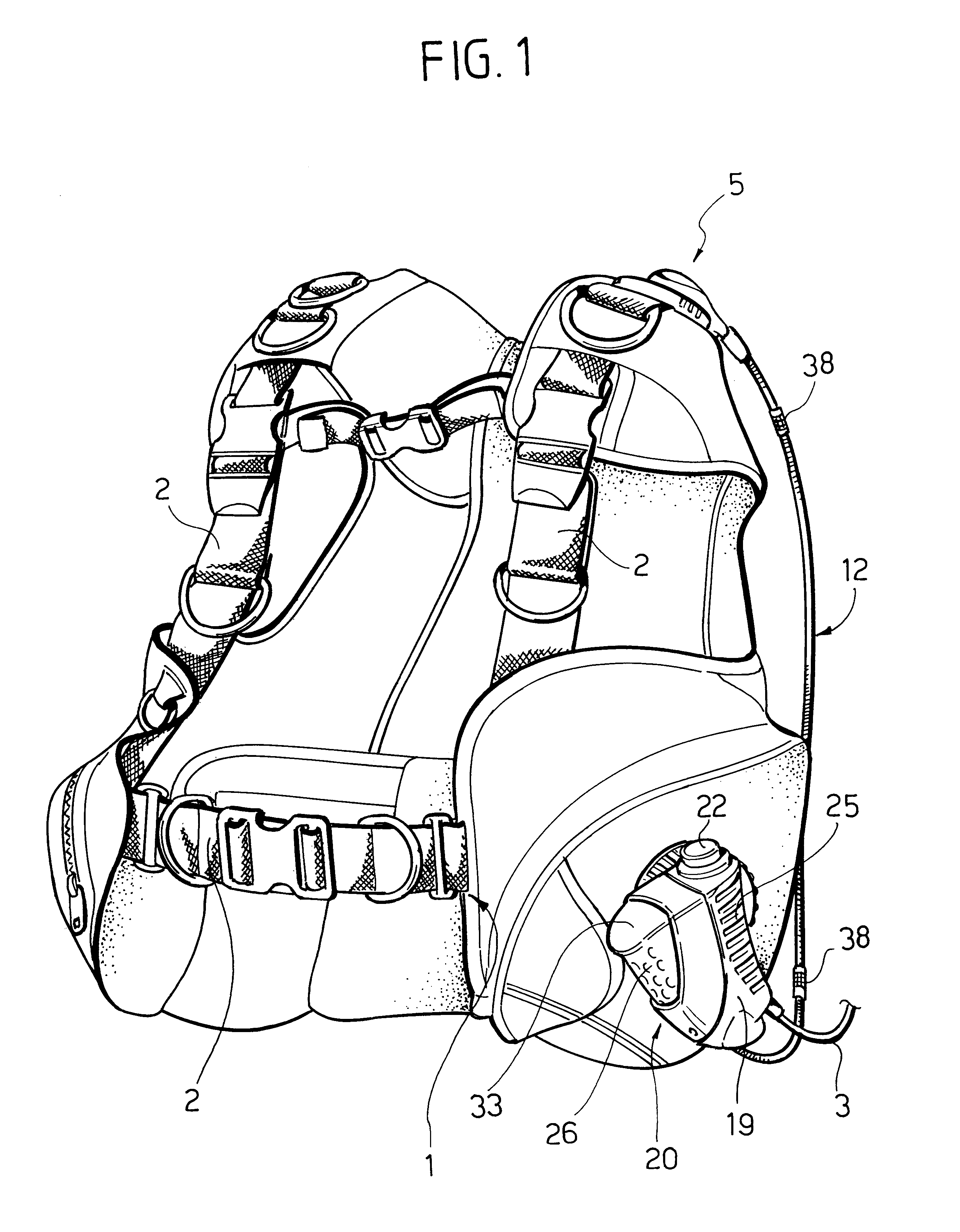
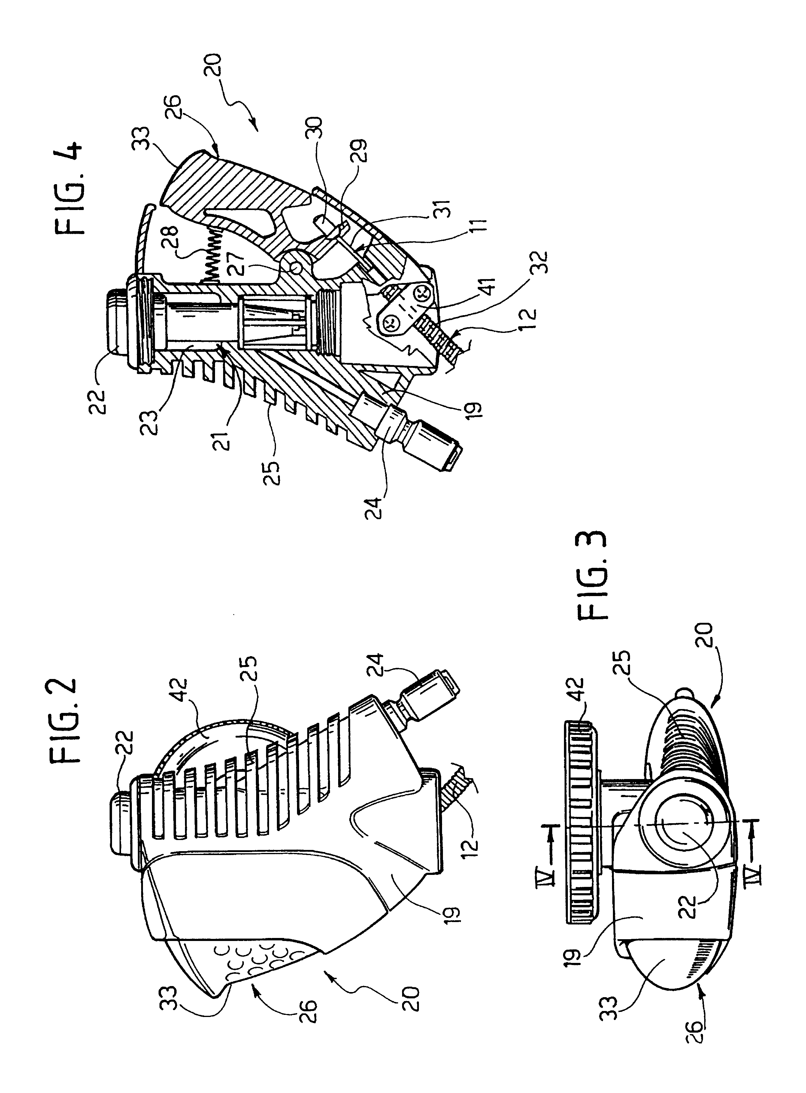
Firstly, the arrangement of the cable within the related freely extending tube makes opening operation of the discharge valve inaccurate and not al all safe: in fact, when the cable is subjected to traction following actuation of the first push-button of the control
assembly, the disharge valve is also being pulled in its entirety, i.e. drawn towards the control
assembly, owing to the limp and flexible nature of the vest tissue on which the valve is secured. Such a displacement of the discharge valve as a whole evidently leads to an unsteady opening performance of the valve, or even to uncomplete or failed opening thereof. On the other hand, the discharge valve is subject to the risk of undesired opening in case the tube along with the cable is housed be pulled from the outside, for instance following accidental
hooking thereof by an
underwater obstacle.
Secondly, the fact that the control assembly is not fixedly secured to the vest is a limit to access ease and convenience for the user.
Thirdly, the inlet path of the inflating air through the long tube provided downstream of the control assembly involves huge losses of pressure downstream of the air expansion site, i.e. after the air has already expanded at a great
specific volume. This rusults in practice into a very slow vest inflating, which is inadequate during regular buoyancy compensations and quite dangerous in
emergency situations.
Recently, the single-bag structure has revealed its serious limits when manufacturers attempted to extend the inflatable area, beyond the ventral region, to include also the rear areas on either side of the compressed-air cylinder.
In these cases, in order to achieve three-dimensional volumes, manufacturers were forced to adopt complex and costly structures on account of the
welding requirements, the said structures moreover being far from effective owing to the small volume even so achieved and the poor "connection" to the diver's body of the floating items, which in practice drift about here and there in the water (see EP-A-0 974 514).
Its only modulating capability is bound to the manual actuating time, which is however really hard to perform in critically difficult
underwater situations.


