
Integrated twist grip shifter

a technology of twisting grip and shifter, which is applied in the direction of linear shaft movement, steering device, cycle control system, etc., can solve the problem that the hand and the separate grip end part may slip off the handlebar

Inactive Publication Date: 2003-07-08
SRAM
View PDF18 Cites 31 Cited by
  • Summary
  • Abstract
  • Description
  • Claims
  • Application Information

AI Technical Summary

Benefits of technology

A further object of the present invention is to increase the protection of the twist grip shift during use by avoiding undesired displacement of the grip end part up with the possibility of slipping off the handlebar.
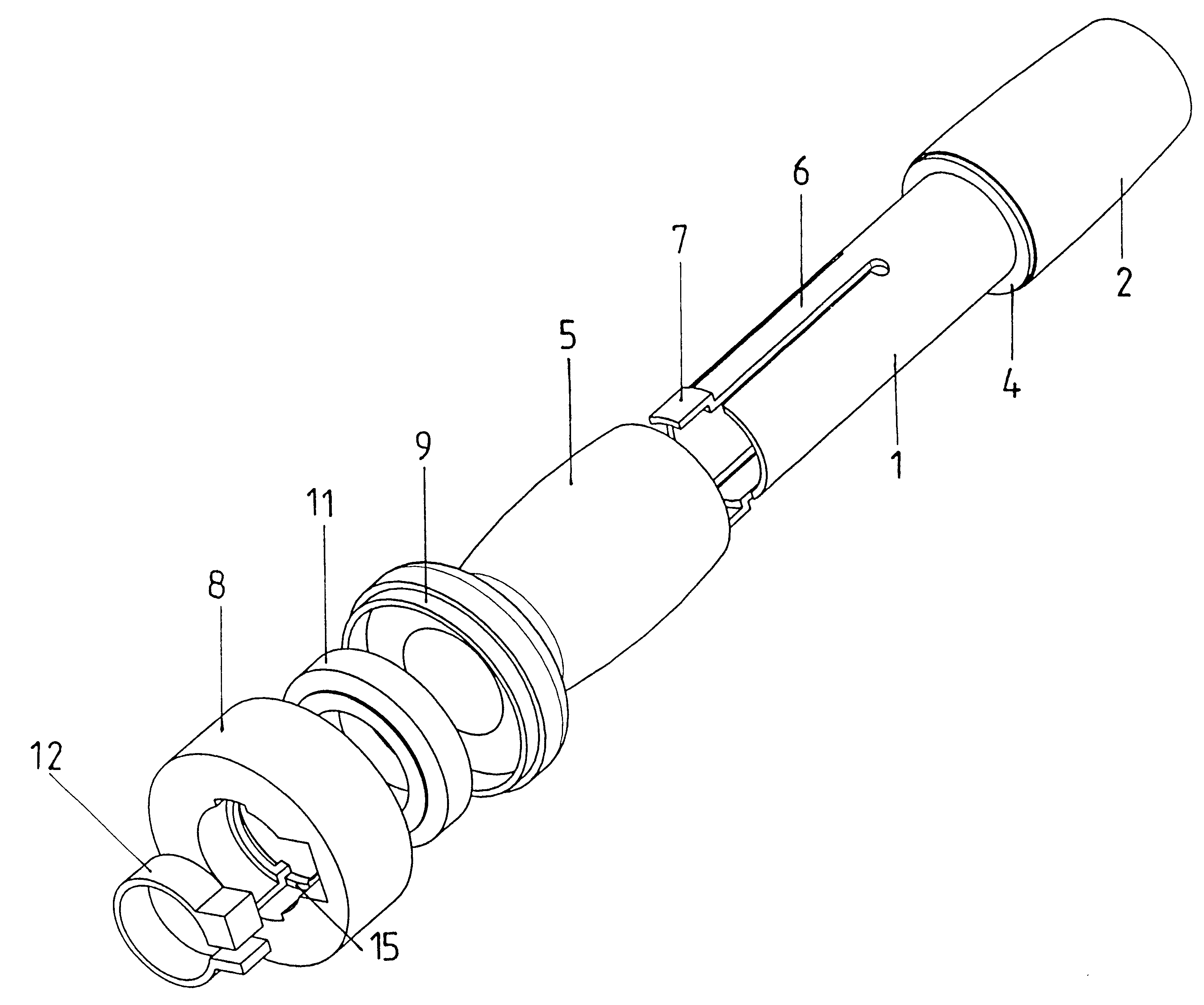
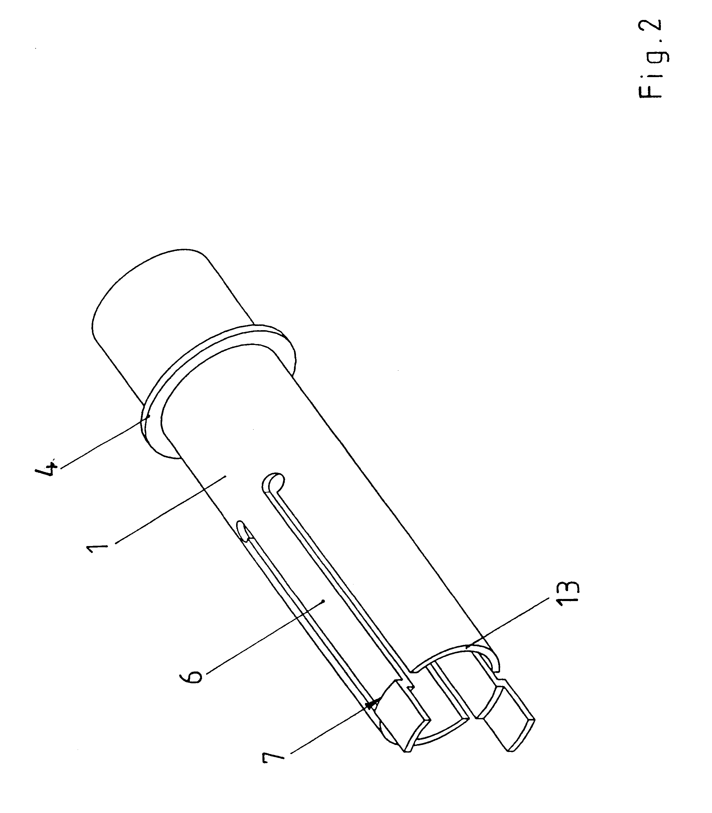
The present invention includes a bearing tube having elastic tongues. The elastic tongues have locking profiles at their respective ends which project in the radial direction to form a positively locking connection with a corresponding profile on a shift housing which protects against twisting and displacement. These elastic tongues allow the twist grip part, the take-up reel and the shift housing to be lined up with the shift mechanism and premounted as an assembly on the bearing tube. This assembly is protected against coming apart unintentionally by the connection between the bearing tube and shift housing. This appreciably reduces the number of twist grip components to be made available and to be mounted for final mounting on the handlebar. The entire twist grip shift is an integral unit which is ready for mounting. A clip is arranged in the internal diameter of the shift housing and may be tightened with an associated screw. Tightening the screw on the clip ensures a secure seat of the twist grip shift including the grip end part on the handlebar. The bearing tube and the twist grip part with the take-up reel are prevented from being dismounted again or disconnected from the shift housing until the clip is removed. To ensure a play-free seat on the handlebar, the internal diameter on the bearing tube and on the grip end part are given appropriately tight dimensions or tolerances. Selective deformation of the internal region may also be used to alleviate the tolerance sensitivity. For example, the inner face of the bearing tube may be of an oval or polygonal shape, instead of circular, to achieve a play-free seat during the adaptation to the round cross section. The oval or polygonal shape is preferably arranged in a region axially adjacent to the elastic tongues. The same effect may alternatively be achieved if the inner region of the bearing tube is equipped with narrow elevations which run essentially in the axial direction. The narrow elevations are deformed during mounting and then seated tightly to provide a play-free seat. Openings may be provided on the bearing tube in the region of the covering of the grip end part so that material projects into the internal diameter of the bearing tube when the grip end part is applied thereto. The material is then appropriately deformed and pressed on during the final mounting of the assembly on the handlebar.

Problems solved by technology

Since the separate grip end part is connected to the handlebar only by friction, there is a remote possibility that the hand together with the separate grip end part may slip off the handlebar during a critical situation.

Method used


Image

  • Integrated twist grip shifter
  • Integrated twist grip shifter
  • Integrated twist grip shifter

Examples


Embodiment Construction

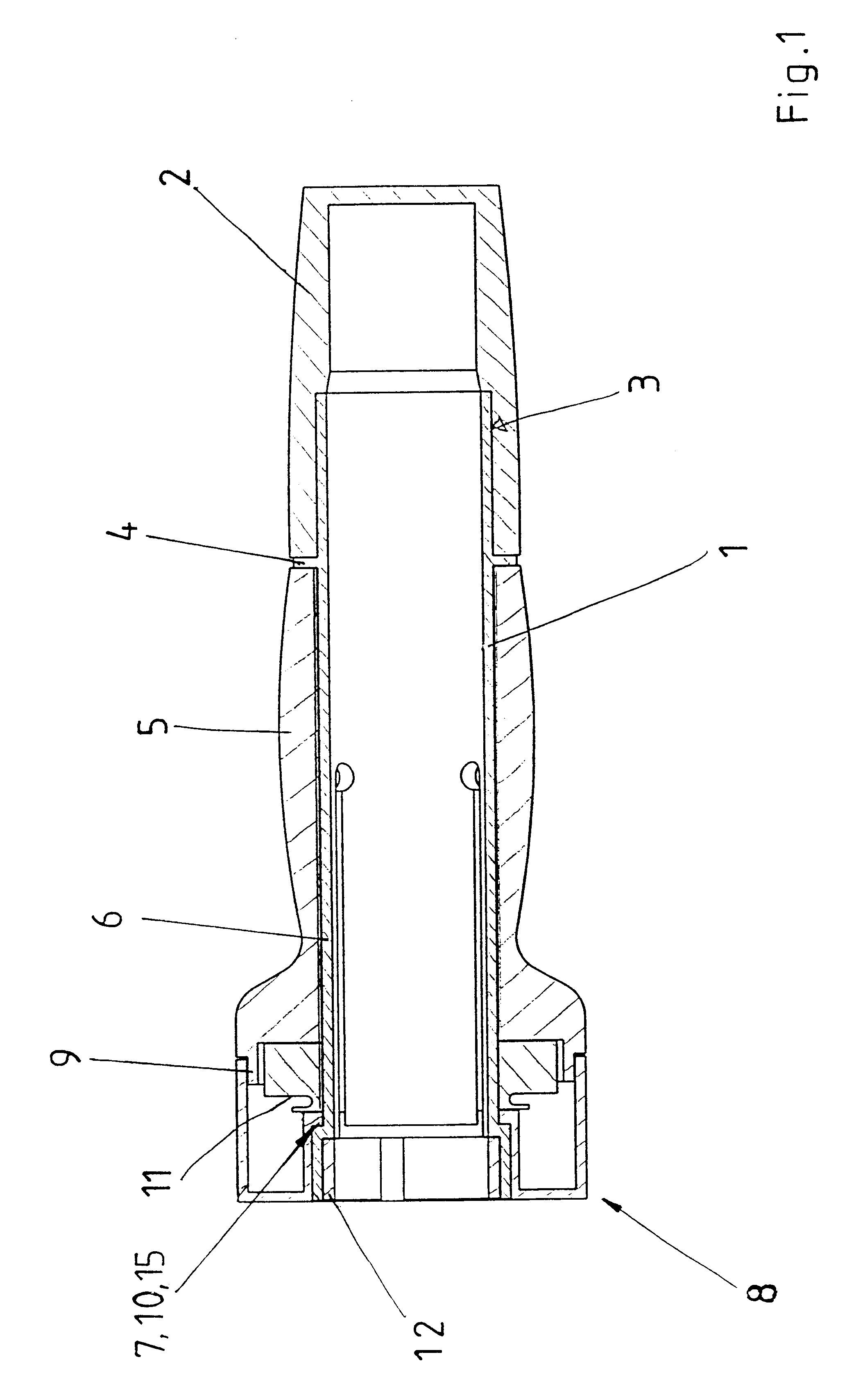
A longitudinal sectional view of a twist grip shift according to the present invention is shown in FIG. 1. The components thereof are essentially arranged around a bearing tube 1 made of, for example, a rigid plastic material. The internal diameter of the bearing tube 1 is dimensioned to ensure a play-free seat on a bicycle handlebar. A grip end part 2 made of an elastomer material is rigidly connected to the bearing tube 1 via an overmolding connection 3 such that the grip end part is fixed with respect to rotation relative to the bearing tube 1. The section of the grip end part 2 which projects beyond the bearing tube 1 has a smaller internal diameter than the bearing tube 1 so that the grip end part 2 is seated free of play or with tension against the end of the handlebar. The external contour of the grip end part 2 has a slightly crowned shape for ergonomic considerations.

An intermediate disk 4 is fixedly seated on the bearing tube 1. Alternatively, the intermediate disk 4 may b...


PUM


Abstract

The invention relates to a twist grip shift which is arranged preferably in the grip region of a handle bar, is secured with a clip and has the purpose of activating bicycle transmissions. The shift components such as the grip end part, the twist grip part, the take-up reel and the shift housing are arranged about a central bearing tube and form one complete grip unit. The clip prevents a releasable connection between the bearing tube and the shift housing from opening in the mounted state. The advantage of this shift design lies in the increase in protection against undesired release of the releasable connection. The components which are joined in the premounted state are securely lined up on the bearing tube.

Description

1. Field of the InventionThe present invention relates to an integrated twist grip shift for shifting gears of a bicycle transmission such as multistage hub transmissions or derailleurs.2. Description of the Related ArtA twist grip shift for controlling a bicycle transmission is disclosed in European Patent EP 0700827 and includes a shift housing with a shift mechanism, a clamping device to be secured to a handlebar of the bicycle, a rotatable take-up reel coupled to a bearing tube for the elastic twist grip part, and a grip end part which is seated on the handlebar so that it is fixed with respect to rotation relative to the handlebar and is also elastic. The separate grip end part is as a rule an elastomer tube which is mounted on the handlebar in a frictionally locking manner and essentially transmits the manual supporting forces onto the handlebar and prevents unintentional shifting operations. A plastic intermediate ring may additionally be arranged between the rotatable twist ...

Claims


Application Information

Patent Timeline
Patent Type & Authority Patents(United States)
IPC IPC(8): B62K23/00B62K23/04
CPCB62K23/04Y10T74/20828Y10T74/20438
Inventor WESSEL, ROBERT
Owner SRAM
Learn More