
Method for profiling and calibrating a digitally controllable printing machine having a permanent printing plate

a technology of printing machine and printing plate, applied in the field of printing machine, can solve the problems of significant machine downtime cost, inconvenient profiling, and inconvenient calibration, and achieve the effect of saving time and material, and avoiding the formation of a false positiv

Inactive Publication Date: 2003-06-17
MANROLANAD AG
View PDF14 Cites 62 Cited by
  • Summary
  • Abstract
  • Description
  • Claims
  • Application Information

AI Technical Summary

Problems solved by technology

The conversion from one color space to another is not without its problems, since color spaces do not overlap in some areas, particular when RGB to CMYK conversions are concerned.
The problem which is presented by a complex output device, such as a printing machine, that the profiles differ depending on the printing material used, the color used, the screen type and screen ruling used and the neutral structure used.
In addition, there is the problem that the selected profiles do not correspond exactly to the current machine condition, but to the condition in which the printing machine was when the profiling was performed.
However, this is costly since it entails machine time and does not produce saleable prints.
On the other hand there are printing systems, for example offset printing machines printing by the anilox process which no longer have such actuating elements or no longer have them to a sufficient extent.
Although this problem exists in all printing devices, it occurs more often in printing machines having permanent printing plates, since these printing machines operate highly productively.
Therefore, significant machine downtime costs occur when re-profiling has to be carried out.
On the other hand, this is because readjustment, which can no longer be handled by means of the machine actuating elements, requires a new printing plate to be created, which likewise costs time and material.

Method used


Image

  • Method for profiling and calibrating a digitally controllable printing machine having a permanent printing plate
  • Method for profiling and calibrating a digitally controllable printing machine having a permanent printing plate
  • Method for profiling and calibrating a digitally controllable printing machine having a permanent printing plate

Examples


Embodiment Construction

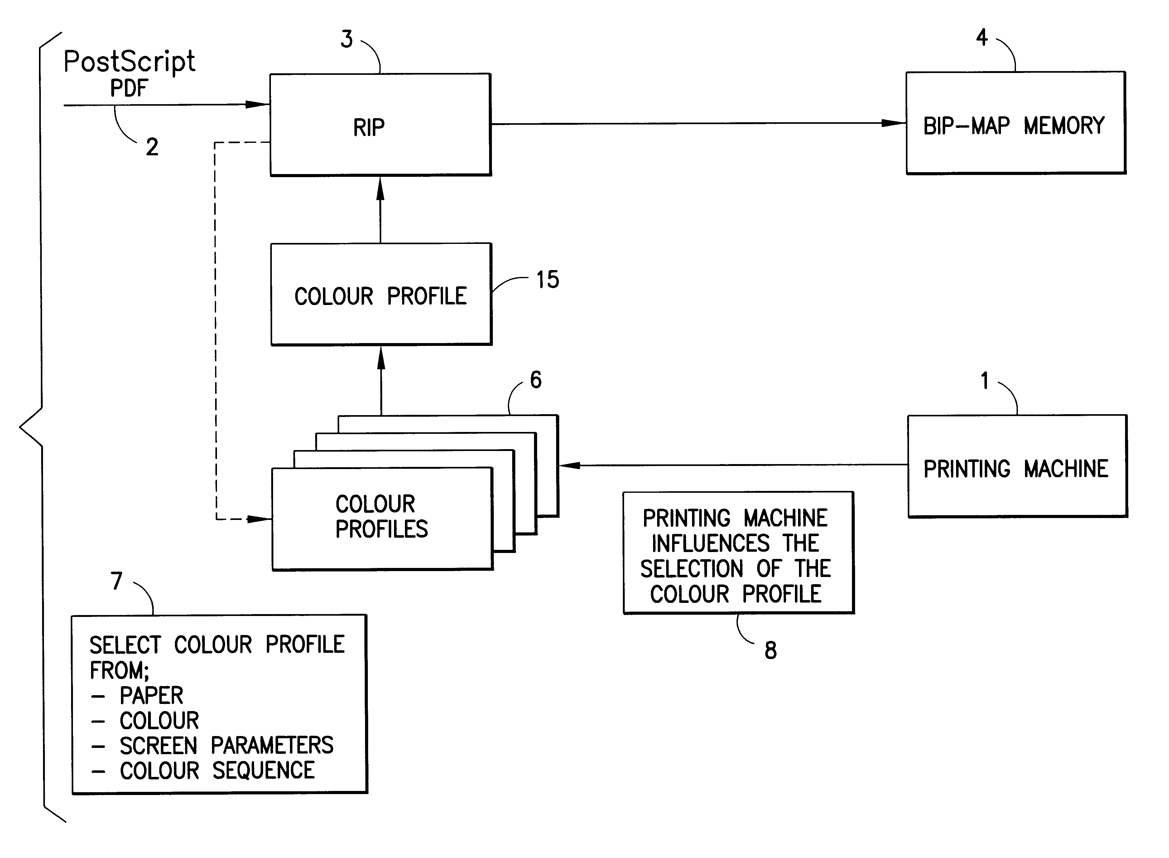
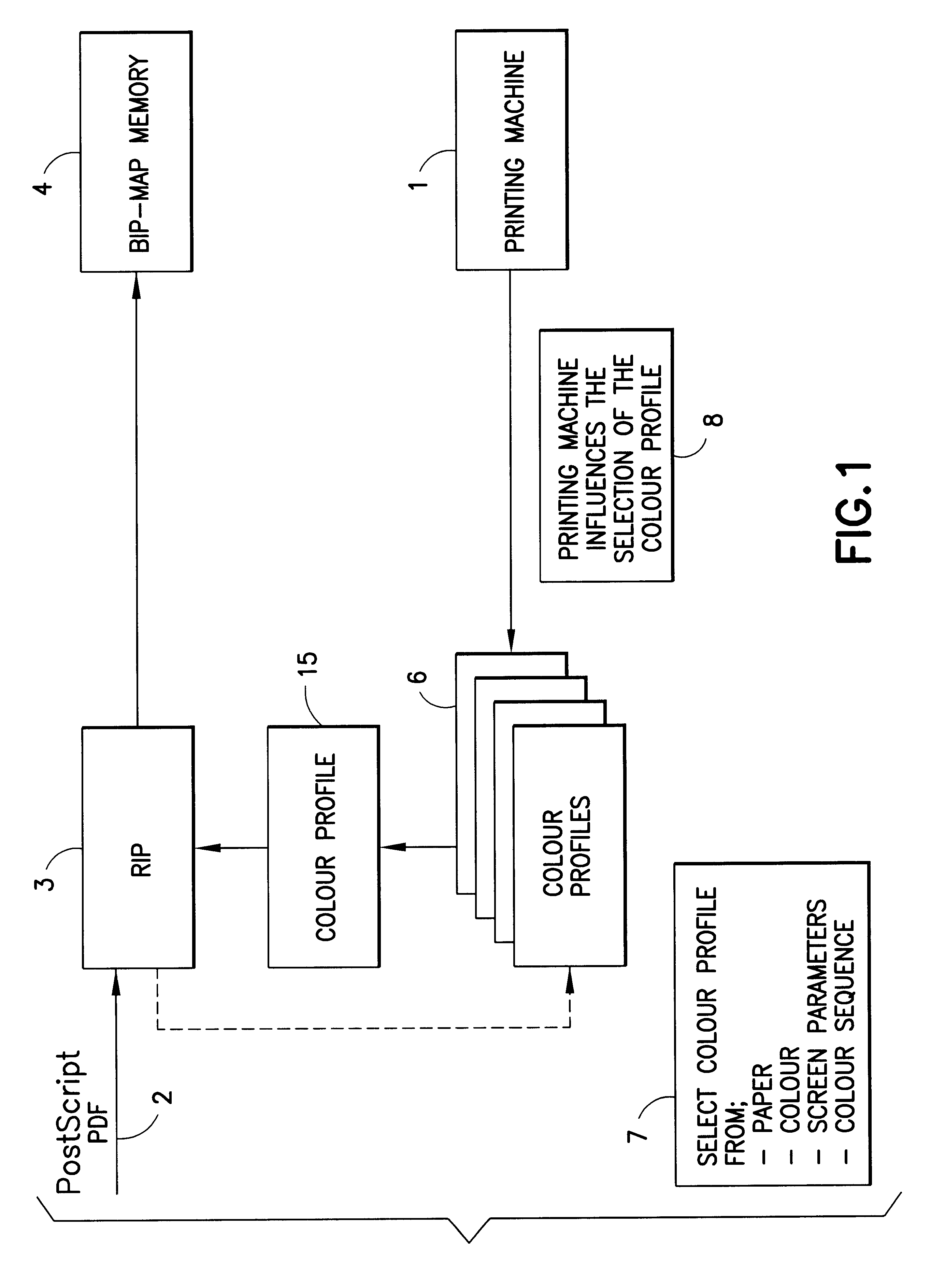
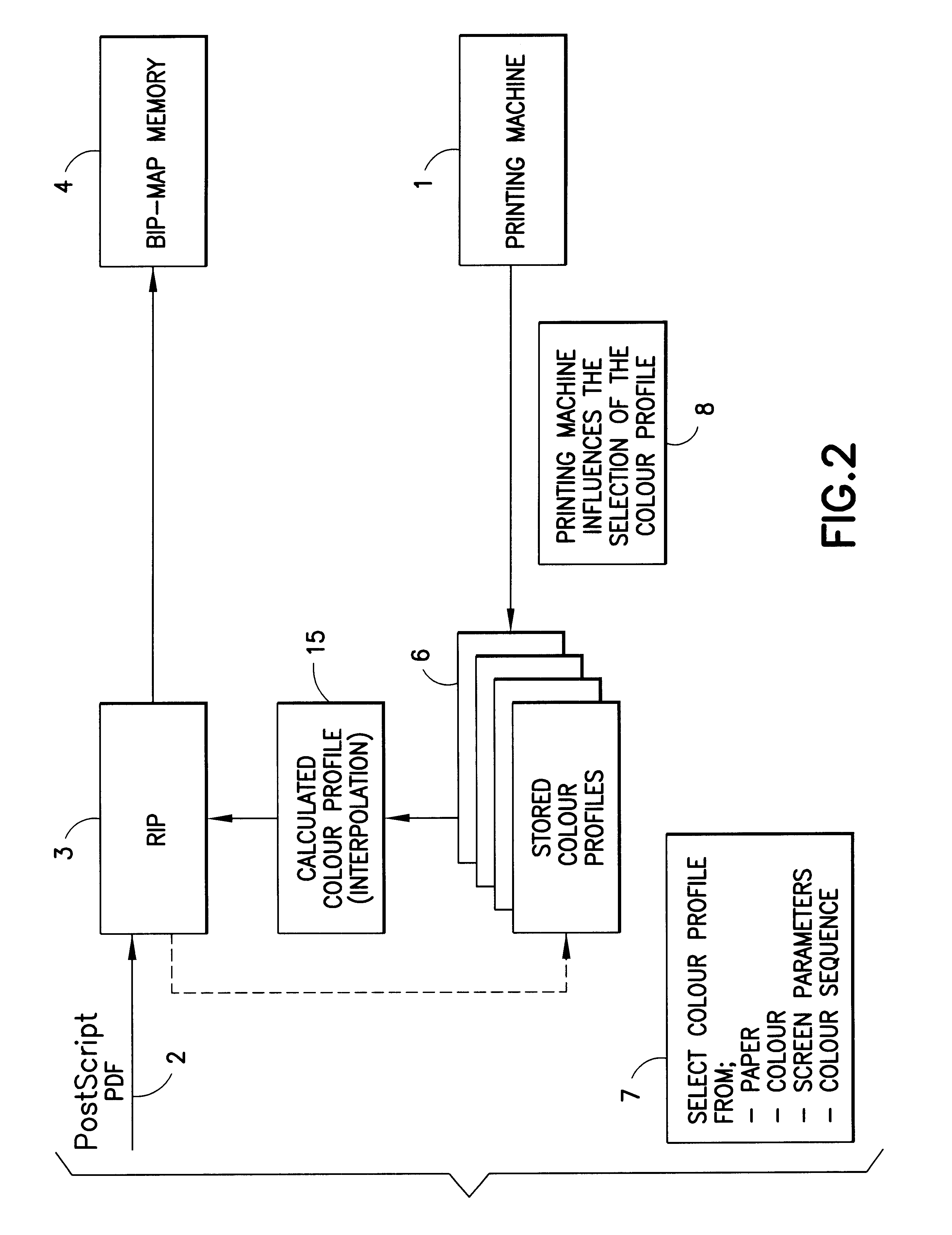
As described previously, a digitally controllable printing machine 1 according to FIG. 1 uses digital image data, which represent the images to be printed and which have been created outside the printing machine in the pre-press stage 70 (FIG. 4) in a machine-independent format, such as in PostScript (PSF) Format 2. The image data is fed to a data processing device, generally an RIP 3, which is assigned to the printing machine 1 and which prepares the image data for the printing process by producing, a digital pixel pattern which is adapted to the printing machine 1 for each color to be printed. Each pixel pattern can be fed, by means of a bit-map memory 4, to the image-setting unit of the printing machine, which then produces a visible printed image pixel by pixel on a substrate.

A number of ink or color profiles 5 are made available in a profile pool 6. These profiles 5 have either already been drawn up by the manufacturer and supplied concomitantly, or have been drawn up by the cu...


PUM


Abstract

A method for calibrating a digitally controllable printing machine having a permanent printing plate, for which image data has been created in machine-independent format in a pre-press stage. The image data is prepared for the printing process by a data processing device and is fed in adapted form to the printing machine 1. The data processing device uses a profile which corresponds precisely with the current machine condition, for the final data preparation for printing. The profile can be addressed using the correct color-space conversion for the printing machine (i.e., calibrated). For this purpose, at the time at which the data is prepared for image setting, a machine condition forecast for the time of printing is called up and, from this, together with the knowledge of the operating materials, the machine profile which most closely approaches that for the print job is determined. This profile is then used for the data preparation.

Description

1. Field of the InventionThe invention relates printing machines, and more particularly to a method for calibrating the image data to the machine condition of a digitally controllable printing machine.2. Description of the Related ArtSuch a printing machine, as disclosed, for example, by DE 295 16 830 U1, operates in particular in accordance with one of the processes of lithographic offset, gravure printing or flexographic printing. That is, a printing plate is generated once with a subject to be printed in order to produce a large number of copies of this subject from this printing plate. It is quite possible for the printing plate to be erasable and reusable (i.e., to have another subject applied to it after cleaning).An essential feature of a digitally controllable printing machine, however, is that the image data which is to be applied to the machine are present completely in digital form, and that these are used in a manner targeted to the printing machine for setting the image...

Claims


Application Information

Patent Timeline
IPC IPC(8): B41F33/16B41F33/00B41C1/00B41F31/02
CPCB41F33/16B41P2227/70
Inventor WEICHMANN, ARMINHUBER, KARLHEINZENKE, GREGOR
Owner MANROLANAD AG
Learn More