
Chromatography device

a chromatography device and chromatography column technology, applied in the direction of filtration separation, separation processes, instruments, etc., can solve the problems of difficult tooling for operators, limited access to the end piece or mounting bolts, and undesirable disassembly of columns

Inactive Publication Date: 2003-06-10
CYTIVA SWEDEN AB
View PDF11 Cites 21 Cited by
  • Summary
  • Abstract
  • Description
  • Claims
  • Application Information

AI Technical Summary

Problems solved by technology

A problem with these mounting methods is that once the net is mounted in a chromatography column then access to the end piece or mounting bolts is limited.
This has the disadvantages that it is time consuming and, for reasons of hygiene, it is undesirable to dismantle a column.
This has the disadvantage that it is difficult for an operator to see the tool when manoeuvring it into place and it is possible for him to inadvertently damage the end piece, net or port while trying to get the tool to grip the end piece.
A further problem is that the heads of the mounting screws, resp. the end pieces, project into the bed media and interfere with the packing of the bed media.
A problem with such an arrangement is that, if the net is made of woven stainless steel, or sintered metal, it is very difficult to obtain a good seal, as the net surface is uneven and the O-ring or gasket cannot deform sufficiently to fill all the irregularities in the surface of the net.
This is particularly problematic if the bed particles used in the column are less than 30 micrometers in diameter or length as they are able to pass through gaps between the O-ring or gasket and the net.
This leads to a loss of bed media through these gaps and a loss of column performance.

Method used


Image

  • Chromatography device
  • Chromatography device
  • Chromatography device

Examples


Embodiment Construction

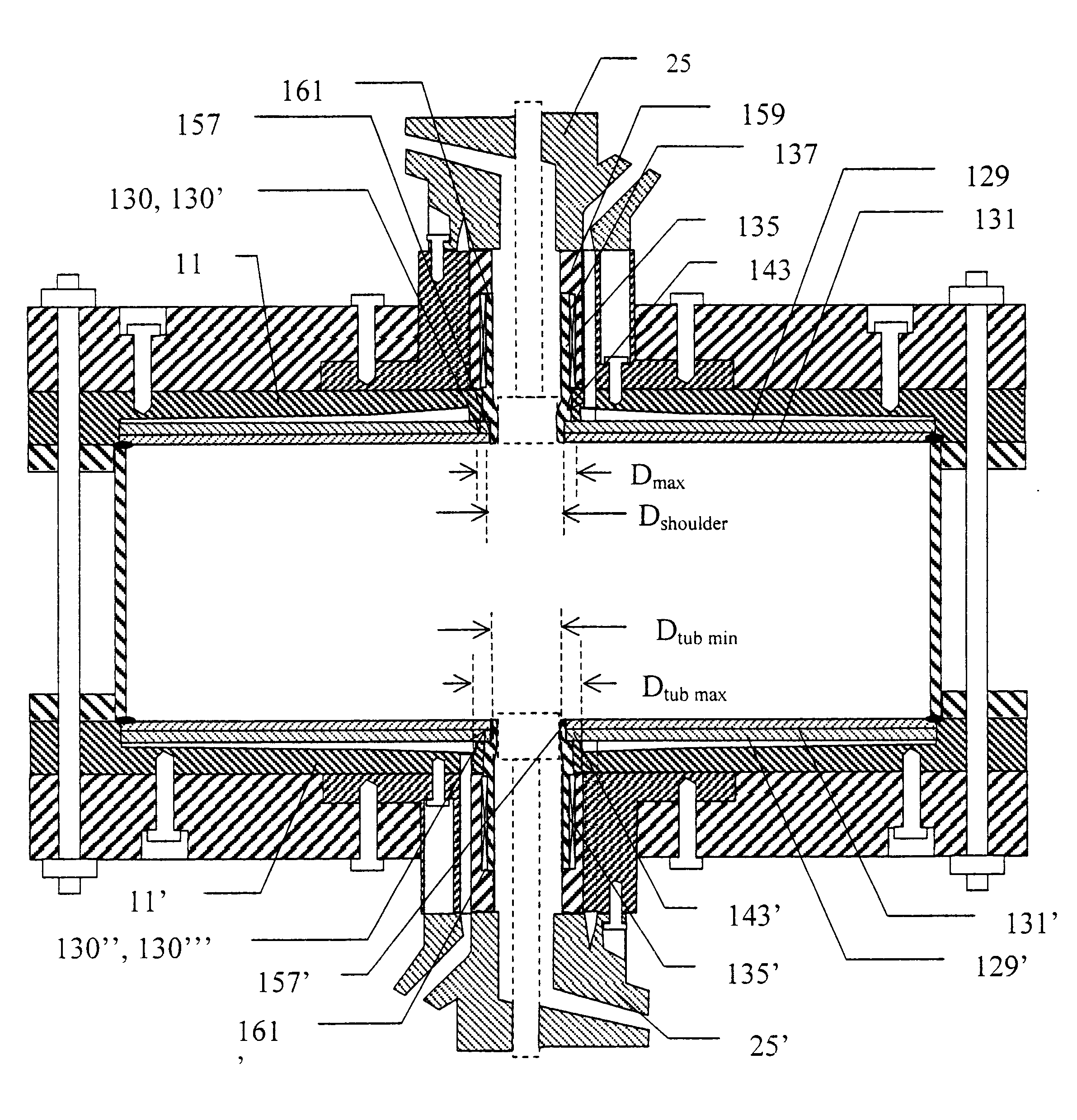
FIG. 1 shows schematically an embodiment of a prior art chromatography column 1. In this example the two ends of the column are substantially identical and either end can be used as the inlet end while the other end is used as the outlet end. For the sake of convenience and clarity of description, it will be assumed that the upper end of the column is the inlet end while the bottom end is the outlet end. Column 1 has a cylindrical wall 3 that has an end plate 5, 5' mounted on it at, respectively, the upper end 6 and the lower end 6' and these are held in place by external longitudinal threaded tie bars 7 with tensioning nuts 9. The space bounded by the wall 3 and end plates 5, 5' is intended to contain a bed medium (not shown). Each end plate 5, 5' supports a distributor cell 11, 11' on its side facing into the column 1. Each distributor cell 11, 11' has mobile phase distributing means, for example radially extending ribs 13, 13', for evenly distributing the mobile phase over the cr...


PUM

PropertyMeasurementUnit
diameteraaaaaaaaaa
circumferenceaaaaaaaaaa
chromatographyaaaaaaaaaa

Abstract

The present invention relates to a chromatography column 1 in which the net 129 and / or bed support 131 is integrally joined to a net retaining means, preferably a sleeve 135 that protrudes through the column end plate 5, and / or to a net retaining circumferential ring. Different net retaining means are also presented.

Description

The present invention relates to chromatography columns and nets for such columns, of the types mentioned in the preambles of the independent claims.PRIOR ARTChromatography columns often contain a net to prevent media from escaping from the end cells which are used for radially distributing the fluid flowing in from a central inlet at one end of the column and for radially collecting the fluid for subsequent outputting from a central outlet at the opposite end of the column. These nets extend across substantially the whole internal diameter of the column. In the prior art the nets have been made of polymer materials and have been attached (with a supporting backing plate if required) to the central inlet resp. central outlet by means of screws or bolts. The screws or bolts are mounted with their heads on the side of the net facing away from the inlet, resp. outlet, and they pass through suitably sized holes in the net and are screwed into suitably threaded axial holes in the wall of...

Claims


Application Information

Patent Timeline
Patent Type & Authority Patents(United States)
IPC IPC(8): B01D15/22B01D15/10G01N30/00G01N30/60
CPCB01D15/22G01N30/6004G01N30/6017G01N30/6026
Inventor PICHL, ULFDAVIS, JOHN
Owner CYTIVA SWEDEN AB
Learn More