
Fiber optic cables having ultra-low shrinking filaments and methods of making the same

a fiber optic cable and filament technology, applied in the field of fiber optic cables, can solve the problems of increasing cable manufacturing costs, shortening fiber optic cable materials, and expensive aramid fibers, and achieve the effect of ultra-low shrinking filaments

Inactive Publication Date: 2003-04-22
CORNING OPTICAL COMM LLC
View PDF42 Cites 27 Cited by
  • Summary
  • Abstract
  • Description
  • Claims
  • Application Information

AI Technical Summary

Problems solved by technology

This demand for fiber optic cables has led to shortages of fiber optic cable materials.
Aramid fibers can, however, be expensive.
This cable can be made of flame retardant materials for riser or plenum applications; however, the cable has disadvantages.
For example, the cable requires a significant quantity of aramid fibers, which are typically expensive, thereby increasing cable manufacturing costs.
Although this fiber optic cable is designed to prevent attenuation induced during the manufacturing process, this design has several disadvantages.
For example, the cable requires a significant quantity of aramid fibers, which are typically expensive, thereby increasing cable manufacturing costs.

Method used


Image

  • Fiber optic cables having ultra-low shrinking filaments and methods of making the same
  • Fiber optic cables having ultra-low shrinking filaments and methods of making the same
  • Fiber optic cables having ultra-low shrinking filaments and methods of making the same

Examples


Embodiment Construction

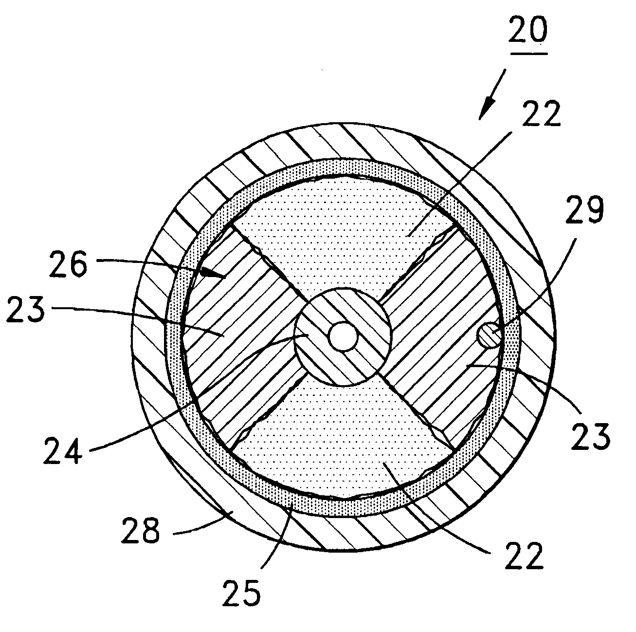
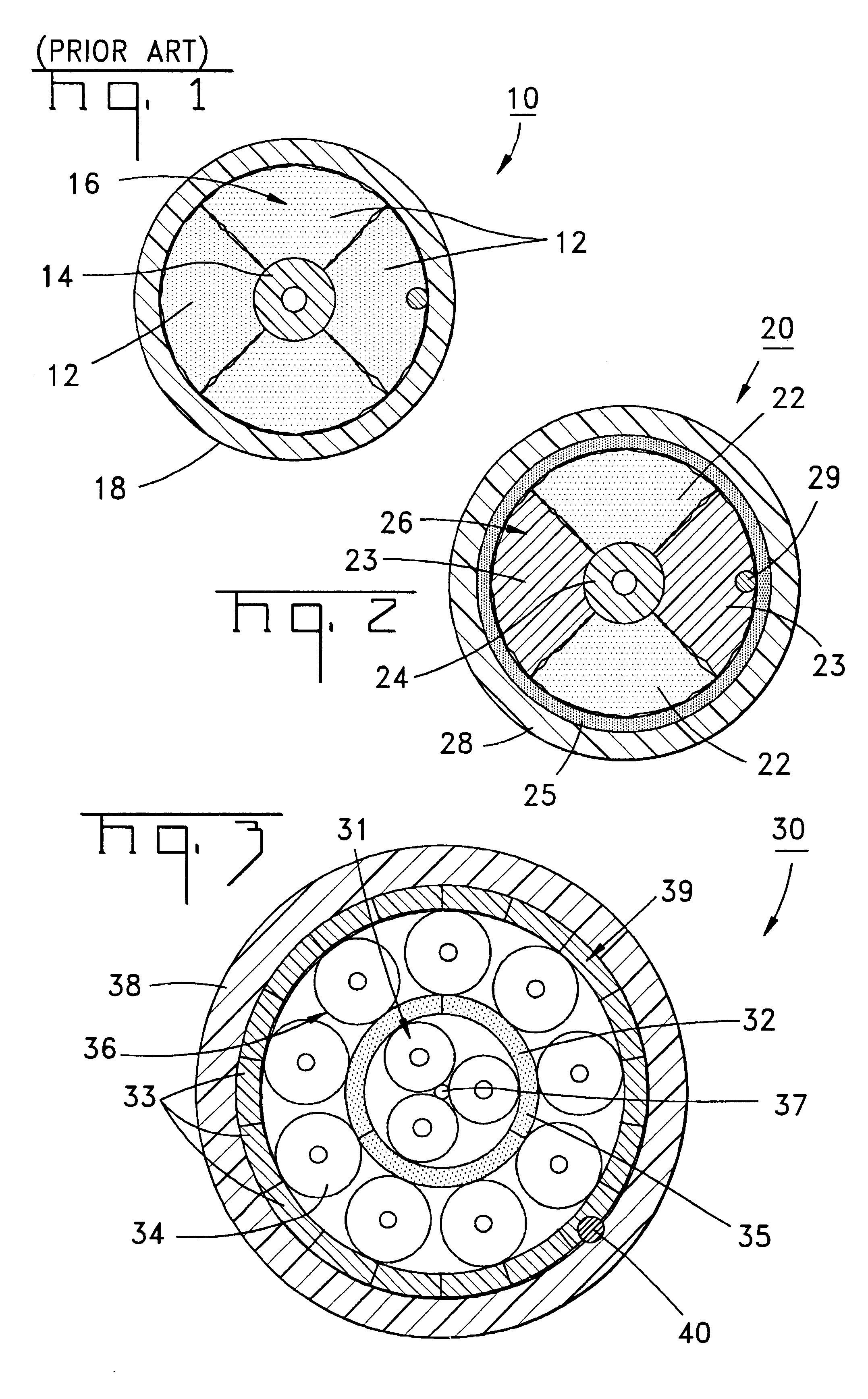
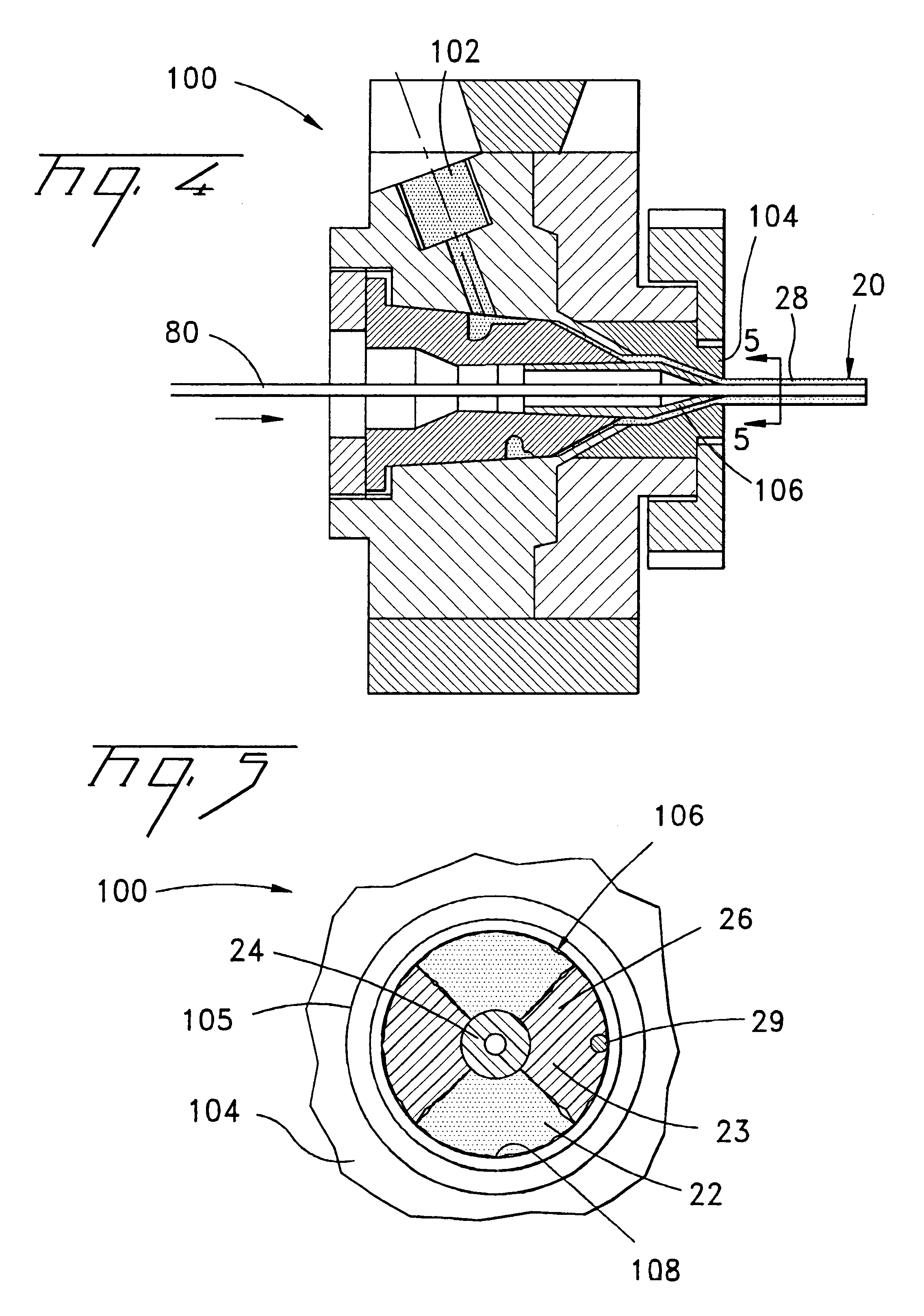
A fiber optic cable 20 according to an embodiment of the present invention is depicted in FIG. 2. Fiber optic cable 20 includes a layer 26 being formed by at least one strength member 22 and at least one ultra-low shrinking filament 23. In one embodiment, layer 26 can be generally disposed between an optical fiber component 24 and a cable jacket 28 that generally surrounds a cable core 80. The at least one ultra-low shrinking filament 23 of the present invention can be used in combination with conventional optical cable strength components in various fiber optic cable designs.

In one embodiment optical fiber component 24 comprises a tight-buffered single-mode optical fiber. However, component 24 can include other optical fiber components, for example, non-buffered fibers, multi-mode tight-buffered optical fibers, loose fibers, ribbonized fibers and / or can include more than one component 24 stranded with or without a central member. Each optical fiber preferably includes a silica-base...


PUM


Abstract

A fiber optic cable and method of manufacturing the same having at least one optical fiber component, at least one strength member and at least one ultra-low shrinking filament. The at least one ultra-low shrinking filament having a shrinkage of about 0.2% or less when heated and held at about 85° C. for about seven days. At least one strength member and at least one ultra-low shrinking filament being disposed generally between the at least one optical fiber component and a cable jacket. The jacket generally surrounding the at least one optical fiber component, the at least one strength member and the ultra-low shrinking filament. The cable can include an interfacial layer interposed between said at least one optical fiber component and the jacket. Additionally, the cable can be riser or plenum rated.

Description

The present invention relates generally to fiber optic cables and, more particularly, to fiber optic cables having ultra-low shrinking filaments.Fiber optic cables include optical fibers that are capable of transmitting voice, video, and data signals. Fiber optic cables have advantages over electrical voice, video and data signal carriers, for example, increased data capacity. As businesses and households demand increased data capacity, fiber optic cables can eventually displace electrical voice, video, and data signal carriers. This demand for fiber optic cables has led to shortages of fiber optic cable materials.Aramid fibers are cable materials that can serve several functions, such as: providing tensile strength to the fiber optic cable; cushioning the optical fibers from compression and impact loads; covering the optical fibers during the extrusion of the outer jacket to prevent the optical fibers from sticking to the extruded outer jacket; and binding the optical fibers togeth...

Claims


Application Information

Patent Timeline
Patent Type & Authority Patents(United States)
IPC IPC(8): G02B6/44
CPCG02B6/4432
Inventor HURLEY, WILLIAM C.SELF, LARRY W.
Owner CORNING OPTICAL COMM LLC
Learn More