
Means of mounting and adjusting telescopic metal tubes

a technology of metal tubes and metal tubes, which is applied in the direction of rod connections, sports equipment, amusements, etc., can solve the problems of not being able to adjust or adjust immediately, and problems that may occur, and achieve the effect of convenient and safe operation

Inactive Publication Date: 2002-09-03
KOMPAN
View PDF3 Cites 16 Cited by
  • Summary
  • Abstract
  • Description
  • Claims
  • Application Information

AI Technical Summary

Benefits of technology

By configuring the interior tube so that it is an expansion body, it becomes possible in this simple manner to tighten this body from without in order to secure the outer tube in a manner which permits adjustment even after instalment of the playground equipment.
As disclosed in claim 2, by configuring the grooves and the wedges with a shape on the sides which slopes towards the outside of the tubes, an evenly distributed expansion of the interior tube against the outer tube is ensured.
As disclosed in claim 4, by providing the wedge body with one or more thread holes extending from without and inwards, and by also providing holes through the outer tube, an outwardly directed tigthening of the wedges is easily and safely obtained by means of bolts through the holes.
Finally, as disclosed in claim 5, it is expedient to provide the interior tube with a base plate at the end, whereby the adjustable assembly can be established at the lower part of the tube where it causes no inconvenience to the user of the playground equipment.

Problems solved by technology

This construction does not permit immediate adjusting or setting and therefore requires a carefully erected base.
Add to this that problems may occur in the event that the foundation subsides or the posts deform which will require the adjusting of one or more of the posts at the base.

Method used


Image

  • Means of mounting and adjusting telescopic metal tubes
  • Means of mounting and adjusting telescopic metal tubes
  • Means of mounting and adjusting telescopic metal tubes

Examples


Embodiment Construction

The invention will be described in closer detail as a column or a supporting tube, for instance by way of a tube in an article of playground equipment.

One or more such tubes constitute the bearing structure to which various playground accessories are secured, such as climbing ropes, slides, ladders, and the like.

Such an item of playground equipment must be firmly secured to its base in order that it will tolerate the often great forces to which it is subjected during use.

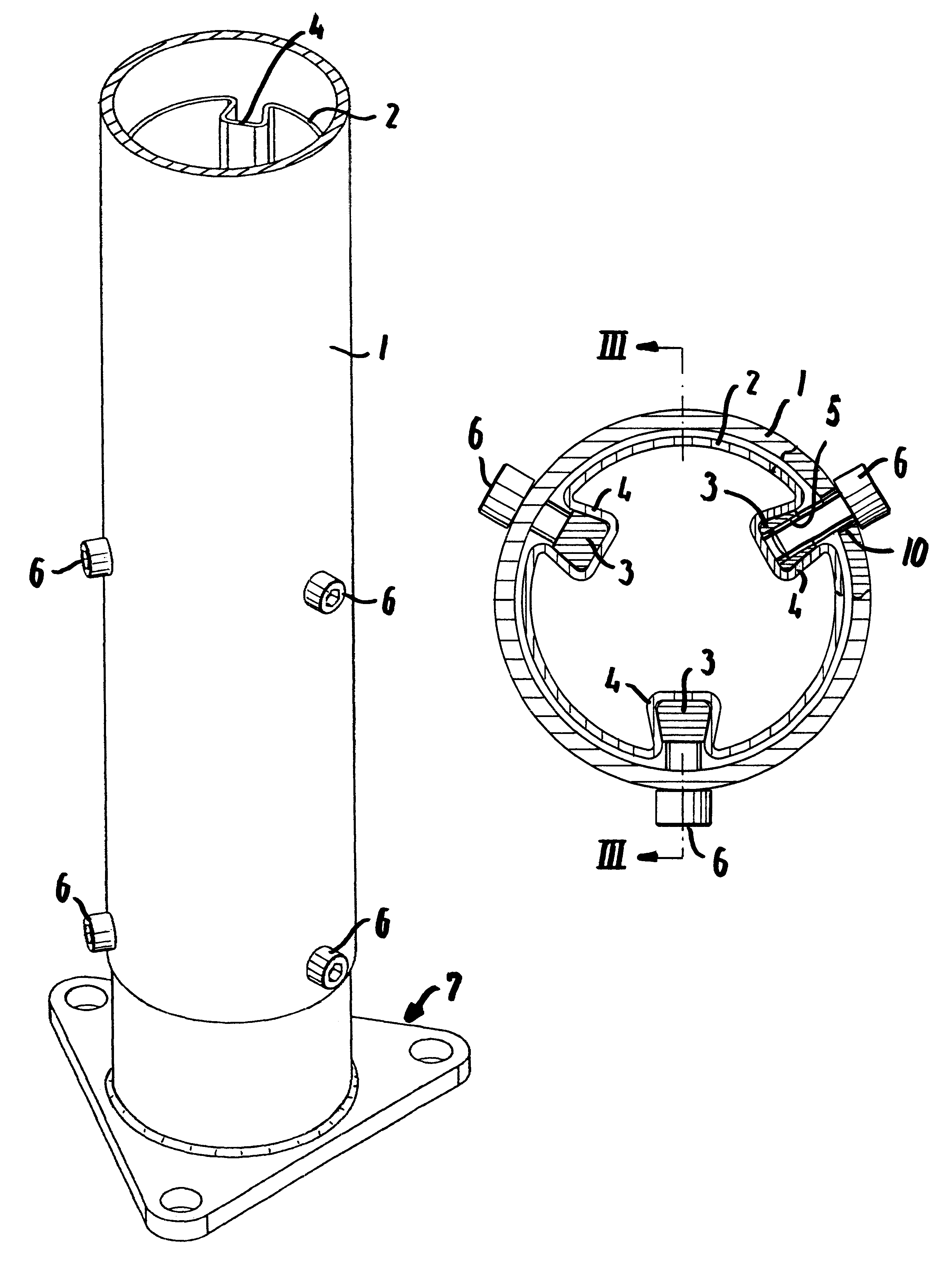
One or more of the tubes may be constructed in accordance with the invention and as shown in FIG. 1, which shows the lower part of a tube 1.

An internally extending tube piece 2 is inserted from beneath into this tube 1, which tube piece 2 for instance by means of a screw / wedge assembly is anchored to a base plate 7 which can be secured to a base which is not shown for instance by means of three bolts.

This base can be a buried or cast anchor, a floor or a footing which constitutes the support. The interior tube 2 may...


PUM


Abstract

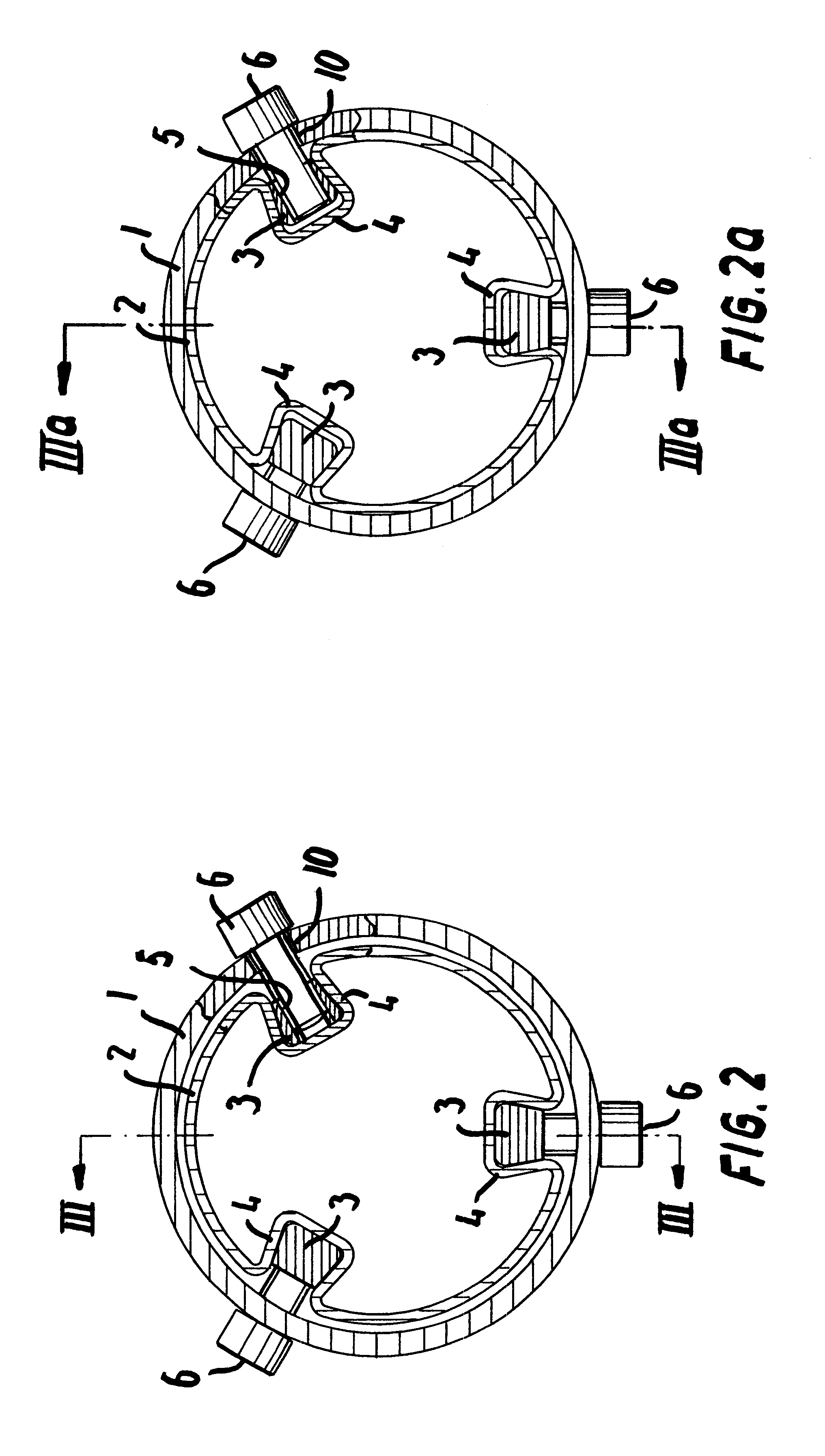
In order to make it easier to mount for instance playground equipment comprising a tube construction which is anchored to a base the subject invention offers a simplification by incorporating a means to facilitate the longitudinal adjustment of the grooves in relation to the base. This means comprises a tube piece (2) extending in the tube (1), which tube piece is anchored to the base and which is configured with longitudinal folds for the formation of outwardly open channels (4). In these channels (4) a wedge element (3) is inserted which by means of bolts (6) through the tube (1) can tighten the wedge and due to the cross sectional shape of the grooves cause the tube piece (2) to expand so that it squeezes against the inside of the tube (1). In this manner the tube (1) can be adjusted in the longitudinal direction in connection with both the mounting and the subsequent adjustment.

Description

THE KNOWN PRIOR ARTThe invention relates to a means of mounting and adjusting two tubes which can slide inside one another.When constructing playground equipment comprising a frame of metal rods or tubes, each metal tube is normally secured to a base in order to provide a stable and safe item of playground equipment.U.S. Pat. No. 6,095,950 discloses an example of such an item of equipment comprising three posts which at their bottom are provided with feet being secured to the base.This construction does not permit immediate adjusting or setting and therefore requires a carefully erected base. Add to this that problems may occur in the event that the foundation subsides or the posts deform which will require the adjusting of one or more of the posts at the base. Any such adjustment will have to be performed by adjusting the actual attachment to the base.OBJECT OF THE INVENTIONIt is the object of the invention to facilitate the installation of the playground equipment as well as the a...

Claims


Application Information

Patent Timeline
Patent Type & Authority Patents(United States)
IPC IPC(8): F16L27/12A63B9/00A63G9/00A63G21/00F16B7/14F16B12/44
CPCF16B12/44A63B9/00Y10T403/7079
Inventor FRANK, JOHN
Owner KOMPAN
Learn More