
Toner supplying container and image forming apparatus

a technology of toner supply container and image forming apparatus, which is applied in the direction of electrographic process apparatus, packaging, instruments, etc., can solve the problems of contamination of the neighborhood with toner, scattering of toner supplied or remaining in the toner supply container, and increasing the contamination

Inactive Publication Date: 2002-08-20
CANON KK
View PDF24 Cites 151 Cited by
  • Summary
  • Abstract
  • Description
  • Claims
  • Application Information

AI Technical Summary

Problems solved by technology

Since the toner is very fine particles, the toner which is being supplied or the toner remaining in the toner supply container might scatter with the result of contamination of the operator or the environment around the apparatus.
However, such a system involves following problems.
Particularly in a system in which the toner supply container is installed in the main assembly of the image forming apparatus,this problem is significant when the toner supply container is taken out before the absence of the is detected, that is, during the toner is being discharged.
In such a state, the container shutter and the main assembly shutter are integrally wedged to effect the sealing, and therefore, the toner enters between the two shutters with the result that outer surface of the shutter of the toner supply container taken out and the neighborhood therefore are contaminated with the toner.
Therefore, by repeating in the removing operations, the contamination gradually increases.
However, the toner discharge opening is relatively small, and the toner supply opening of the toner supply device which receives the toner, and therefore, the access thereto from outside is very difficult.
In such a system, it is difficult to remove periodically the accumulated toner in the toner supply device.
If the thickness of the seal portion 16t is larger than 0.3 mm, the follow-up property relative to the container shutter 16 is not enough with the result that sealing property is not sufficient, and if it is not more than 0.1 mm, stable molding is difficult.
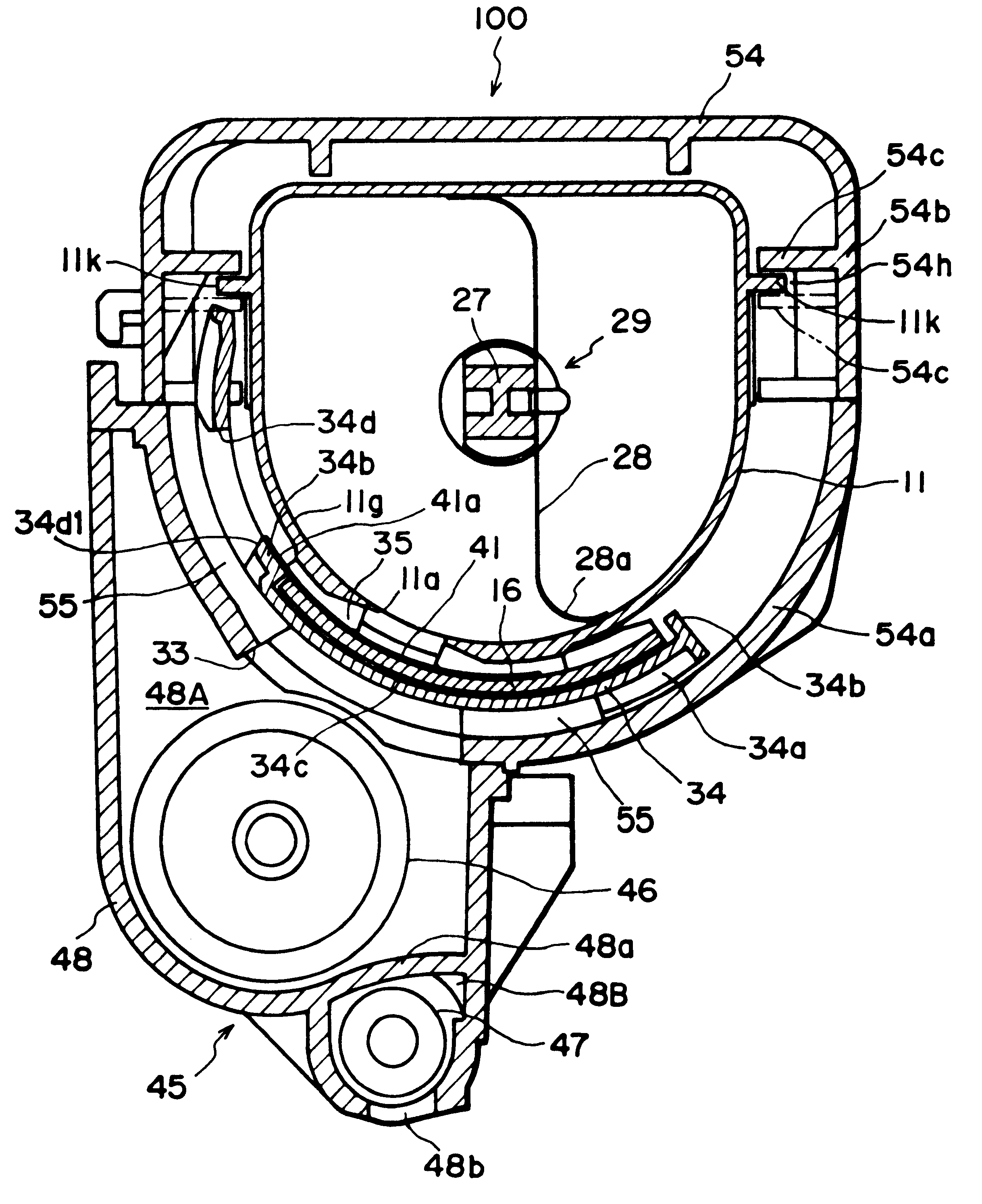
As a result, various problems occur while the toner supply container 1 is handled, in particular, while the toner supply container 1 is installed into, or removed from, the toner supplying apparatus 100.
However, such a structure makes the shutter stroke substantially longer, making it difficult to give a toner supplying apparatus and a toner supplying container a compact design.
If the extended portion 41a is too short, the performance of preventing enters of the toner is not sufficient, and the pocket-like portion formed between the seal member 41 and the toner container 11 is shallow, and therefore, the retention of the toner therein is also insufficient.
If the rigidity of the seal member 41 is increased, the transmission of the urging force is possible even if the extended portion 41a is long, but the follow-up property to the main assembly shutter 34 is not sufficient also with the result of deterioration of the hermeticality.
Furthermore, the main assembly shutter opening 34d becomes narrow so that passage of the toner is impeded.

Method used


Image

  • Toner supplying container and image forming apparatus
  • Toner supplying container and image forming apparatus
  • Toner supplying container and image forming apparatus

Examples


embodiment 2

{Embodiment 2}

In this embodiment, the toner discharging opening is sealed when there is no packing member between the toner discharging opening and the container shutter. FIGS. 46-51 show this embodiment.

FIG. 46 is a longitudinal sectional view of a toner discharging opening of the toner supply container. In Embodiment 2, there is not a packing member 35 (FIG. 13) which encloses the toner discharging opening 11a. Even in this case, the same advantageous effects are provided.

FIG. 46 shows a sealed state before start of use, and the toner discharging opening 11a is sealed by sealing film 36 in place of the packing member 35 in Embodiment 1. The film 36 is heat-welded around the toner discharging opening 11a so as to be removable therefrom. The material of the film may be any known heat-weldable film. In this embodiment, the use is made with a seal bar (unshown) comprising a polyester film having a thickness of 16 .mu.m, a biaxial orientation Nylon film having a thickness of 25 .mu.m a...

embodiment 3

{Embodiment 3}

FIGS. 52-54 are enlarged front sectional views of a toner supply device according to Embodiment 3 of the present invention, in which FIG. 52 shows a state in which the toner discharging opening is closed during mounting and demounting of the toner supply container, and FIG. 53 shows a state in which the shutter is being opened, and FIG. 54 shows a state in which the toner is being supplied out.

In this embodiment, the outer surface of the toner supply container 1 is not cylindrical but is a simply flat surface. With this structure, the same advantageous effects as with Embodiment 1 can be provided.

FIG. 52 shows the sealed state before start of use, and in the Figure, the same reference numerals as Embodiment 1 are assigned to the elements having the corresponding functions, and the detailed description thereof are omitted.

During the toner supply operation, the toner supply container is mounting into the toner receiving device, and the container shutter 16 is brought int...


PUM


Abstract

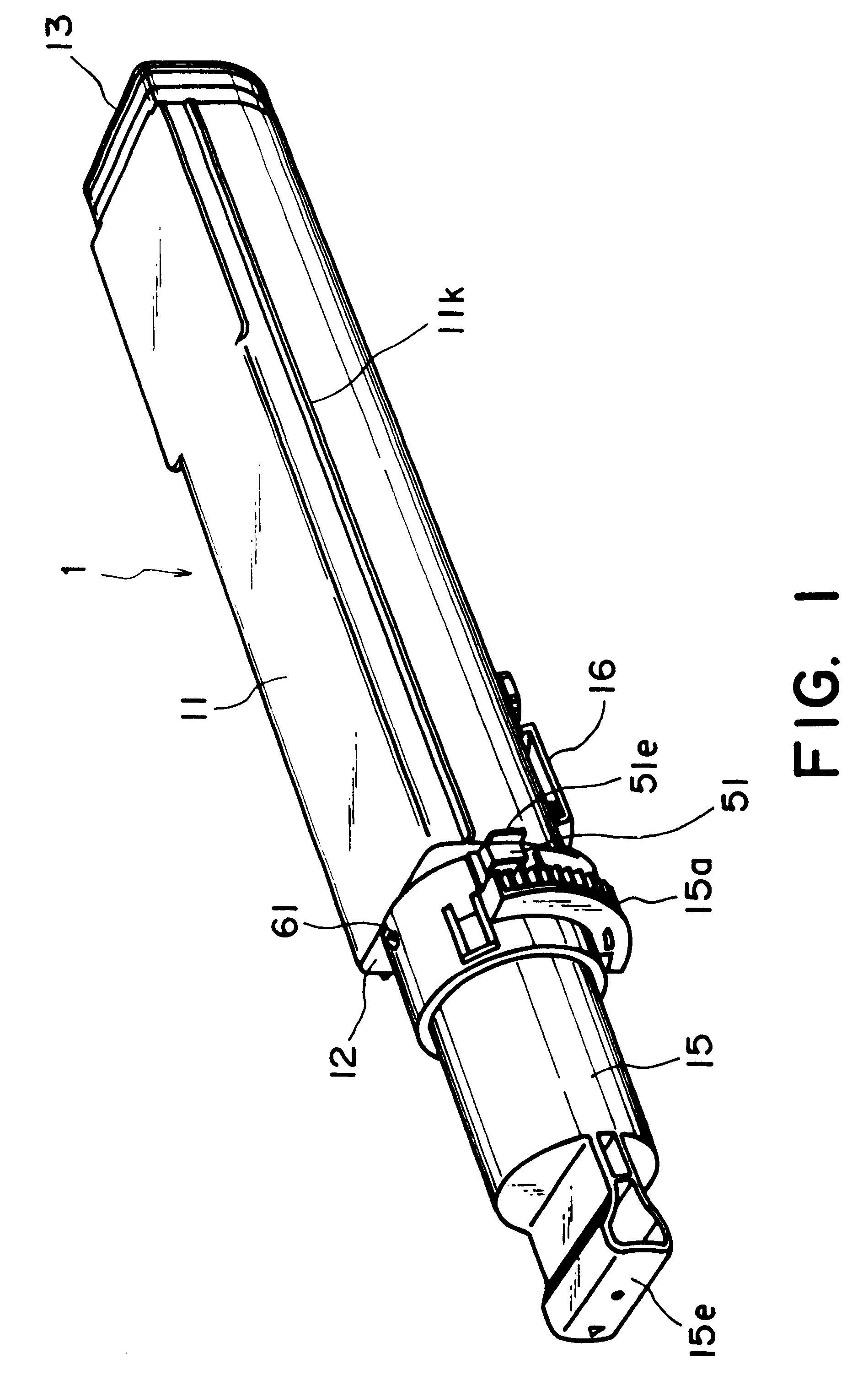
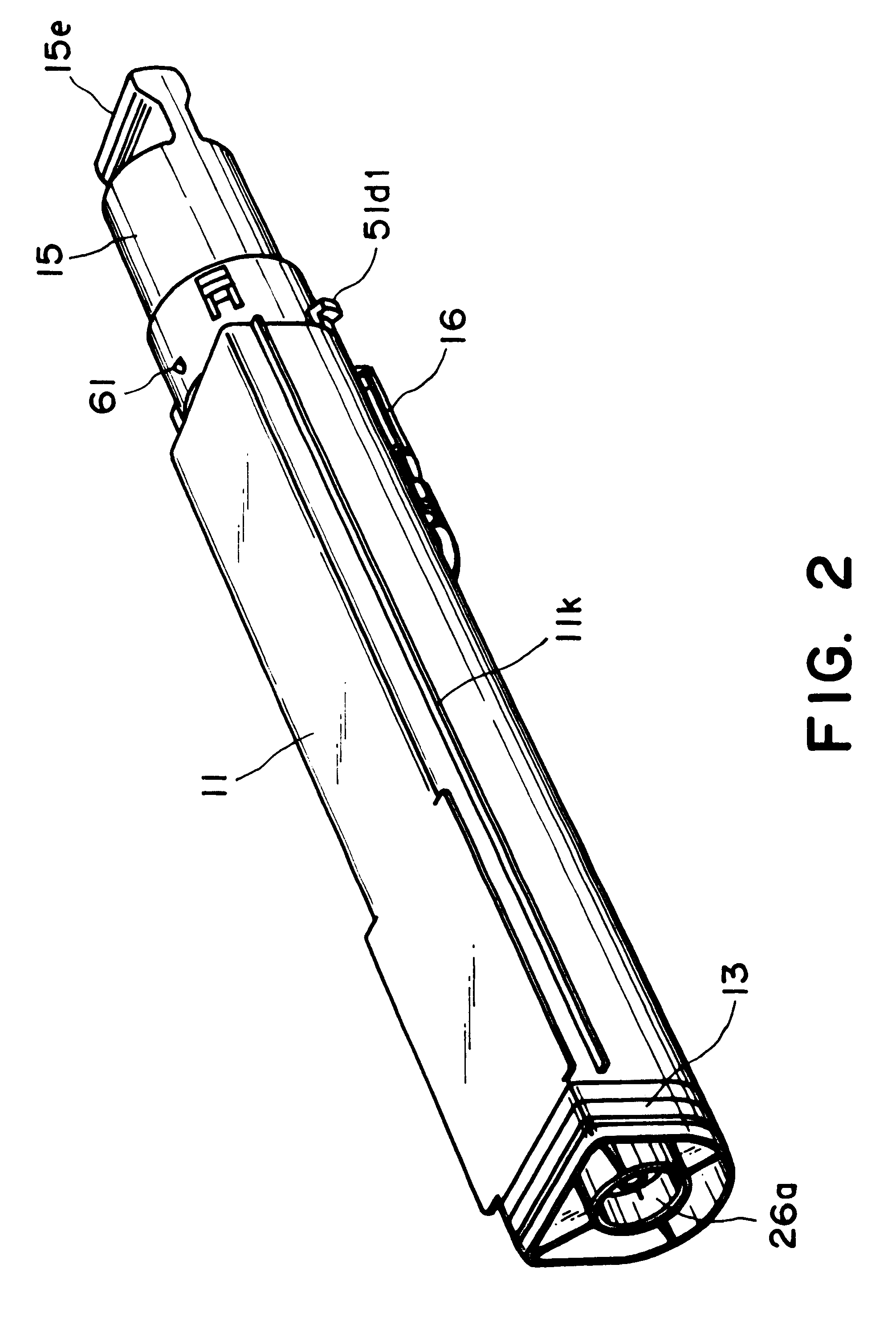
A toner supply container, detachably mountable to a main assembly of an image forming apparatus, for supplying toner to the main assembly of the image forming apparatus. The toner supply container includes a main body for accommodating the toner; a discharging opening for permitting discharging of the toner accommodated in the main body of the container; a container shutter member for opening and closing the discharging opening, the container shutter member being provided with an engaging portion engageable with a main assembly shutter member provided in the main assembly of the apparatus, wherein the main assembly shutter member is openable and closable relative to a toner reception opening of the main assembly of the apparatus while the container shutter member and the main assembly shutter member are interrelated with each other, and wherein the engaging portion is capable of passing by a position corresponding to the discharging opening; cover seals covers the engaging portion relative to the discharging opening.

Description

FIELD OF THE INVENTION AND RELATED ARTThe present invention relates to an image forming apparatus such as an electrophotographic copying machine, a printer or the like and a toner supply container for supplying toner to the image forming apparatus. Here, typical examples of the image forming apparatus include an apparatus which forms an image on a recording material through an electrophotographic image formation process. Examples of the electrophotographic image forming apparatus include an electrophotographic copying machine, an electrophotographic printer (laser beam printer, LEDprinter, for example), a facsimile machine, a word processor or the like. In the image forming apparatus such as the electrophotographic copying machine, the printer or the like, a developer in the form of fine powdery toner is used. When the developer (toner) in the main assembly of the image forming apparatus, is used up, the toner is supplied into the main assembly of the image forming apparatus using a...

Claims


Application Information

Patent Timeline
IPC IPC(8): G03G15/08G03G15/00
CPCG03G15/0875G03G15/0886G03G15/0865G03G15/0855G03G2215/068G03G2215/0692Y10S222/01G03G15/00
Inventor BAN, YUTAKAGOTO, TATSUYAKANAMORI, AKIHITOTAZAWA, FUMIO
Owner CANON KK
Learn More