
CAM type hub and strut for use in portable and semi-permanent structures

a technology of portable and semi-permanent structures and hubs, which is applied in the direction of rod connections, traffic signals, roads, etc., can solve the problems of frequent damage to the hub system or the structure itself, the inability to properly utilize the extra diagonal length between the rod or strut ends and the distance between the corners of the panel, and the unit becomes very difficult to set up

Inactive Publication Date: 2001-10-02
BUSHNELL HLDG
View PDF10 Cites 99 Cited by
  • Summary
  • Abstract
  • Description
  • Claims
  • Application Information

AI Technical Summary

Problems solved by technology

The shortcomings of the current art device centrally hubbed units lie in the impracticality of utilizing the proper amount of extra diagonal length between the rod or strut ends and the distance between corners of a panel.
When the struts used are of optimal length, the unit becomes very difficult to set up, and damage to the hub system or structure itself frequently occurs.

Method used


Image

  • CAM type hub and strut for use in portable and semi-permanent structures
  • CAM type hub and strut for use in portable and semi-permanent structures
  • CAM type hub and strut for use in portable and semi-permanent structures

Examples


Embodiment Construction

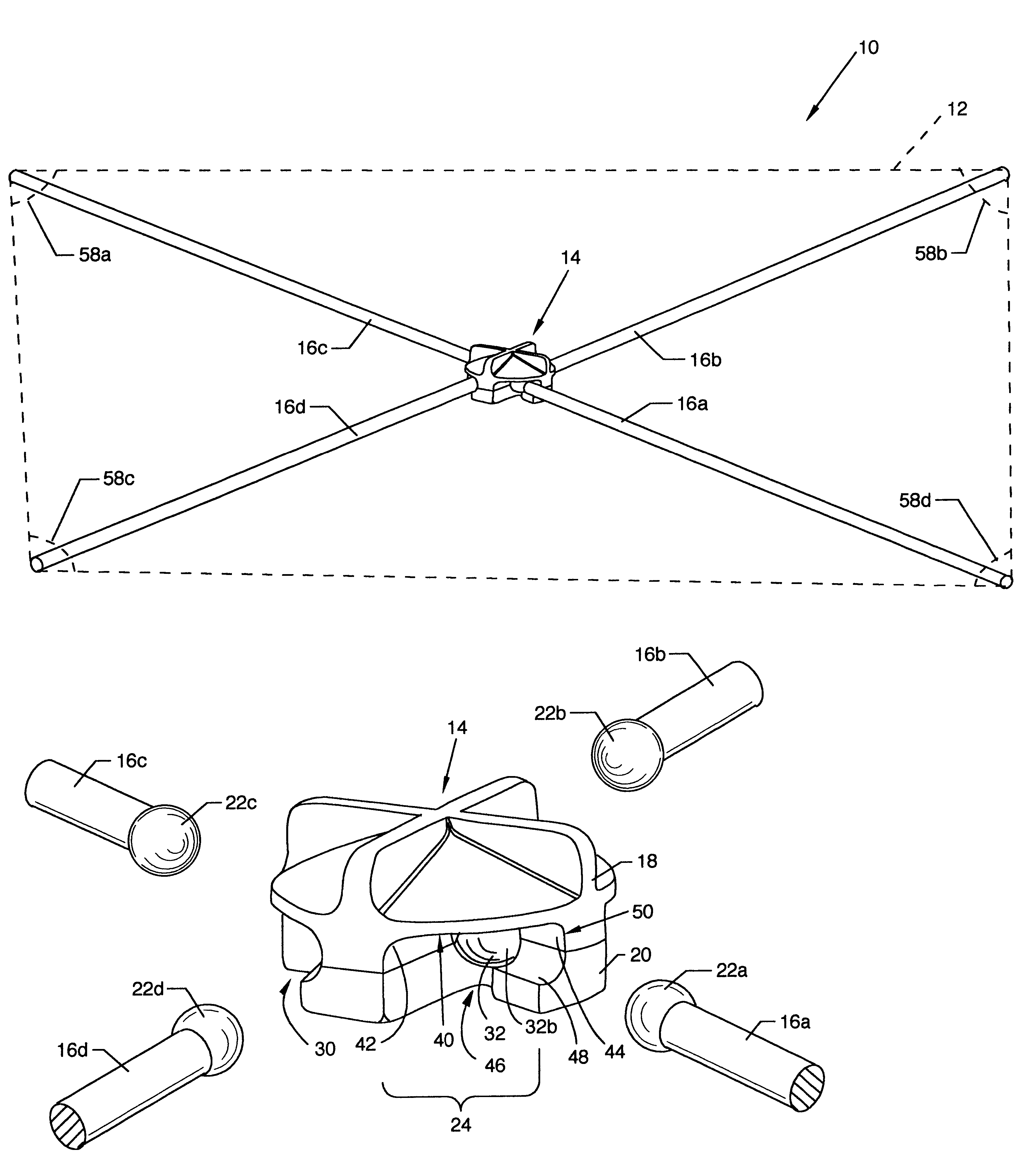
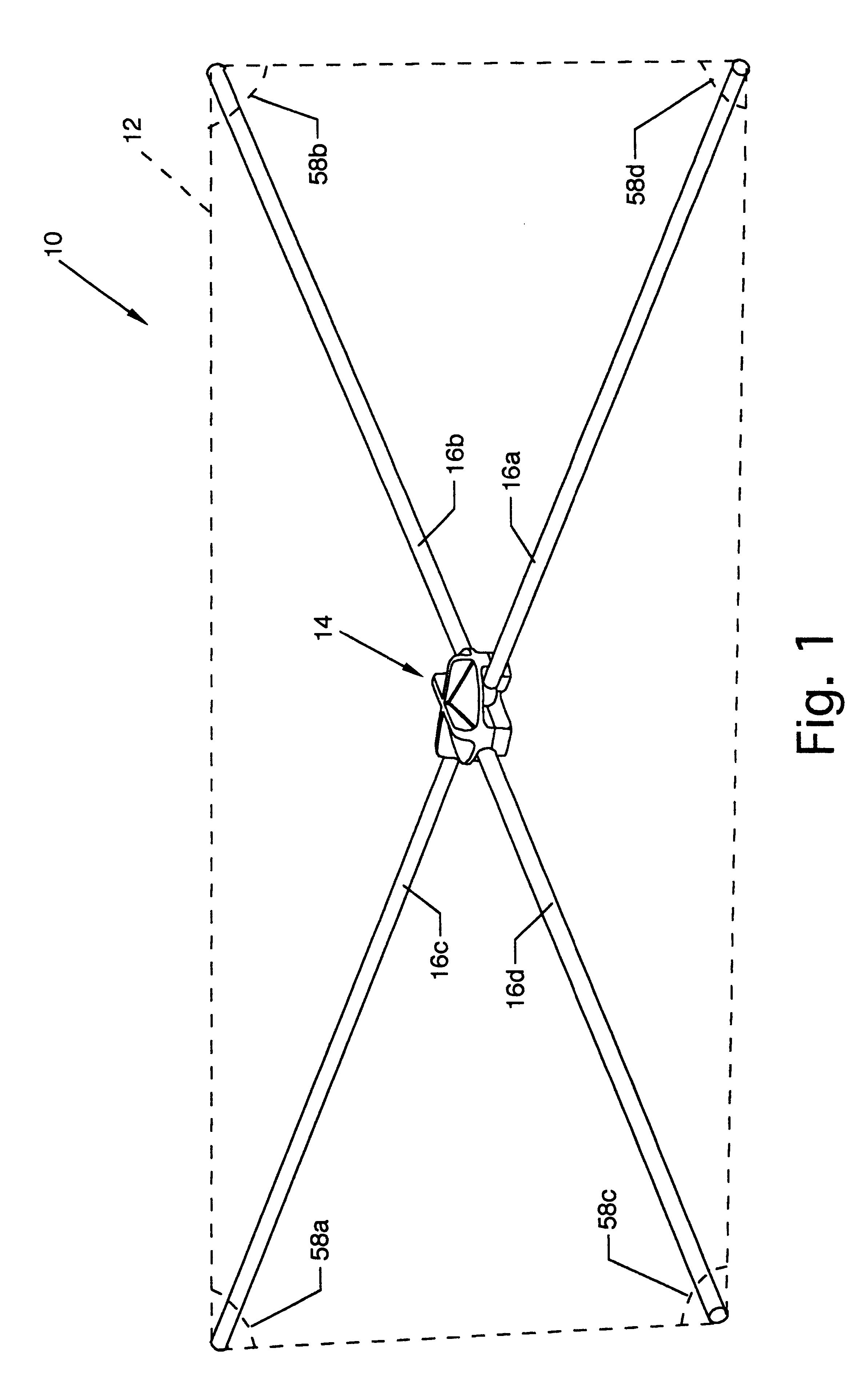
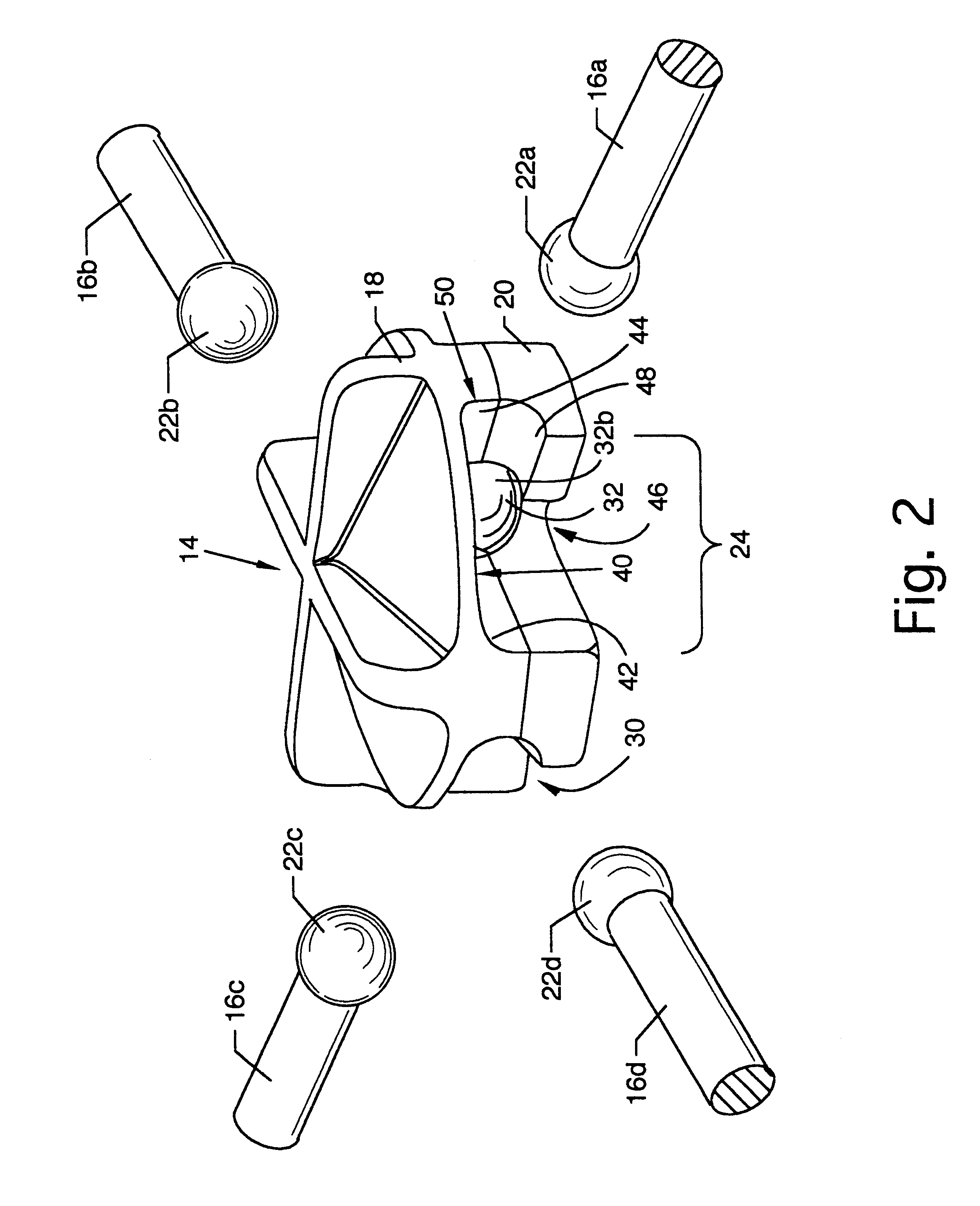
FIG. 7 illustrates a bottom view of the hub 14 accommodating the inboard ends of struts 16a-16d. The outboard ends of the struts 16a-16d extend to the end of a panel such as panel 12 shown in FIG. 1 and are secured or captured thereto or therein. The struts 16a-16d are rotated, for purposes of illustration and example, to the fullest counterclockwise position about the respective ball ends 22a -22d, and are limited in travel in a counterclockwise position by one side such as the arced surface 42 of the accommodational maneuvering channels 24, 26, 28 and 30, respectively, and to also lie against the planar surfaces of the accommodational maneuvering channels 24, 26, 28 and 30, such as planar surface 40. In addition, the inboard strut ends of the struts 16a-16d are also aligned to the truncated slots 46. The position of the struts 16a-16d is shown in the relaxed and non-actuated position and the hub 14 is also shown in the relaxed and non-actuated position. Also referenced in the draw...


PUM


Abstract

A cam style hub and strut system for use in single panel fabric, cloth, or plastic units, or structures with an unlimited number of wall and / or roof panels. The purpose of the cam style hub is to compensate for certain fabric characteristics and to allow easier setup of structures containing flexible or rigid support struts connected to a central hub by lessening the distance of the diametrically opposing struts during assembly, and applying the force necessary to engage the self-supporting structure by engaging the cam, increasing the distance between the ends of the opposing struts. The amount the distance is increased can be dictated by materials used and the size of the panel. The hub may contain an optional "locking" feature activated when the hub cam is engaged for convenience and safety reasons. The principle can be used with any number of struts greater than one.

Description

CROSS REFERENCES TO CO-PENDING APPLICATIONSNone.1. Field of the InventionThe present invention is for a support system, and more particularly, pertains to a cam style hub and strut system for use in portable and semi-permanent structures. The present invention can be used in any number of structures, including but not limited to, portable or semi-permanent structures, such as ice fishing houses, movie screens, road crew signs, boat covers, tents, medical tents, hunting blinds, photography blinds, portable garages, and the like.2. Description of the Prior ArtPortable or semi-permanent structures are popular and practical for many of the aforementioned applications. The shortcomings of the current art device centrally hubbed units lie in the impracticality of utilizing the proper amount of extra diagonal length between the rod or strut ends and the distance between corners of a panel. The diagonal distance between opposing strut ends must be sufficiently greater than the corresponding...

Claims


Application Information

Patent Timeline
Patent Type & Authority Patents(United States)
IPC IPC(8): E01F9/012E01F9/011E04B1/344E04H15/48E04H15/34
CPCE01F9/0122E04B1/3441E04H15/48Y10T403/341Y10S135/901Y10T403/32336E01F9/654
Inventor JOHNSON, BROOKS E.BEAM, KEITH J.
Owner BUSHNELL HLDG
Learn More