
Mounting bracket

a technology for mounting brackets and antennas, which is applied in washstands, lighting support devices, instruments, etc., can solve the problems of difficult or even impossible for a single installation engineer to provide such mounting of antennas against poles in practi

Inactive Publication Date: 2001-09-04
INTEL CORP
View PDF6 Cites 215 Cited by
  • Summary
  • Abstract
  • Description
  • Claims
  • Application Information

AI Technical Summary

Benefits of technology

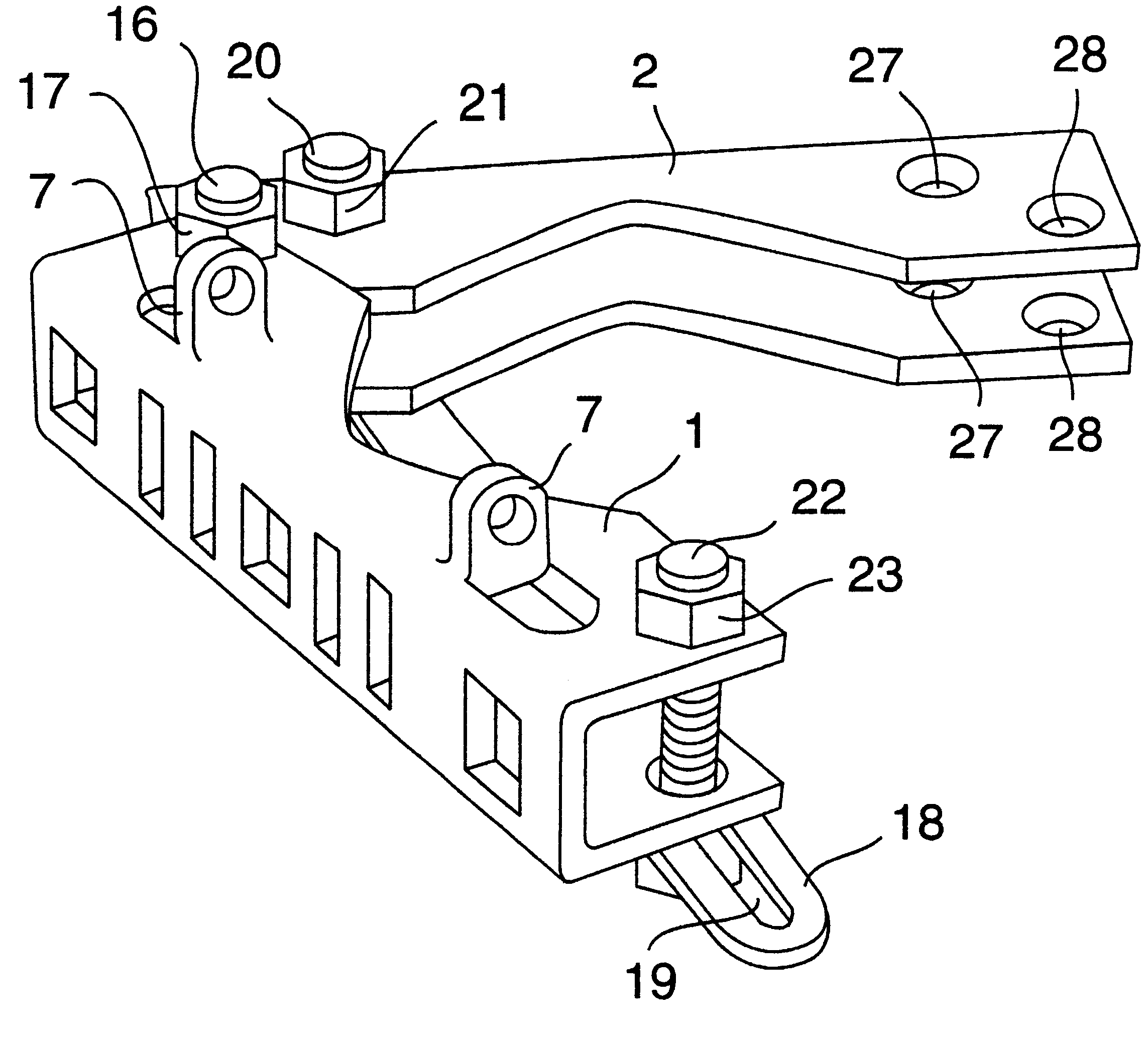
By connecting the base clamp and the tightening clamp with a rotating joint, e.g. in the form of a hinge and fastening the tightening clamp to a supporting structure, such as a wall, it is achieved that the antenna can be panned, i.e. its rotational position in respect of its vertical longitudinal axis can be adjusted to a desired value.

Problems solved by technology

It is obvious that it is, in practice, very difficult or even impossible for a single installation engineer to provide such mounting of an antenna against a pole, and it is often necessary that the mounting is made by two installation engineers, one installation engineer carrying the antenna and the second installation engineer pulling and tightening the screw-nut joint between the two clamp parts.

Method used


Image

  • Mounting bracket
  • Mounting bracket
  • Mounting bracket

Examples


Embodiment Construction

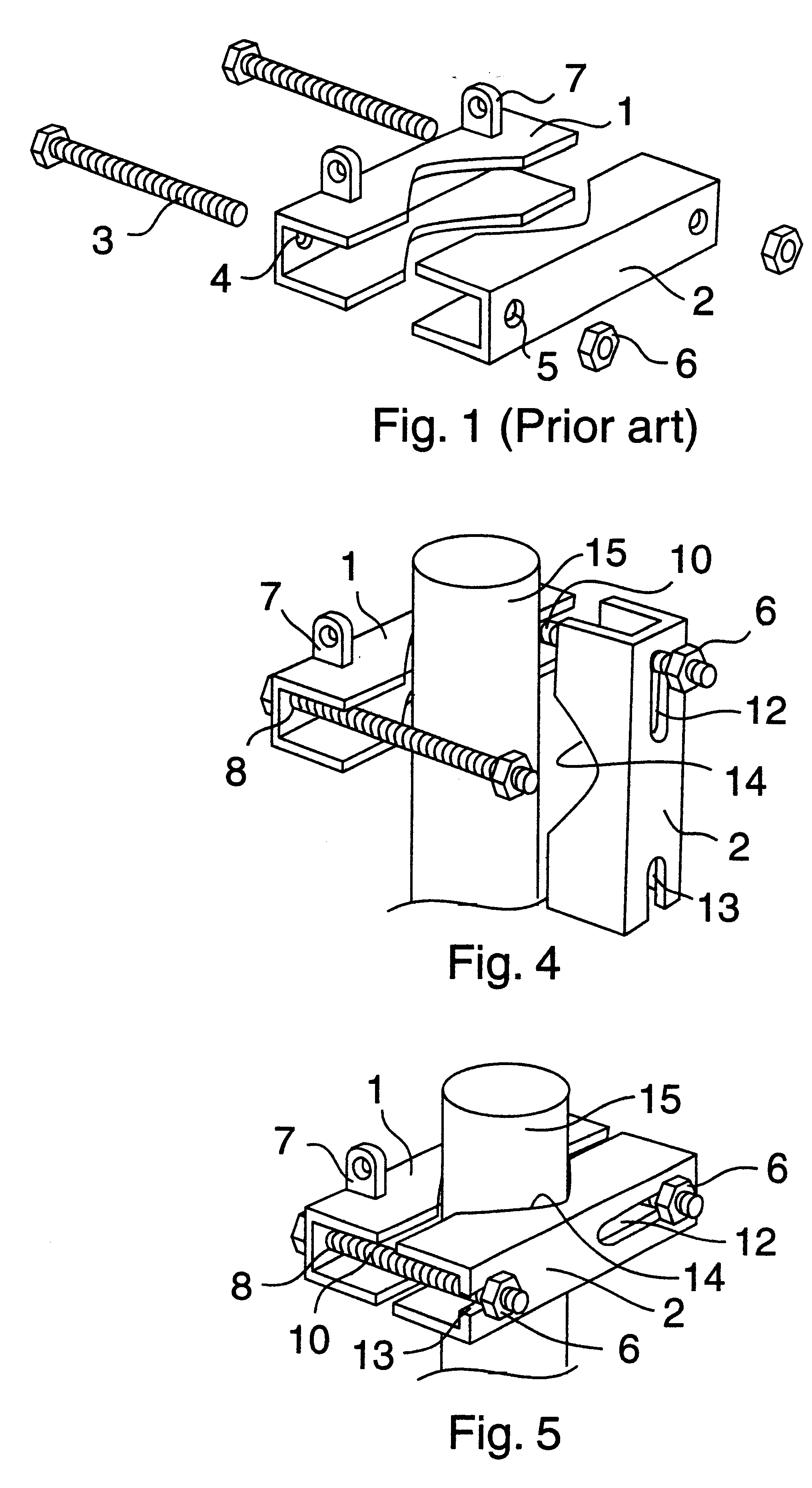
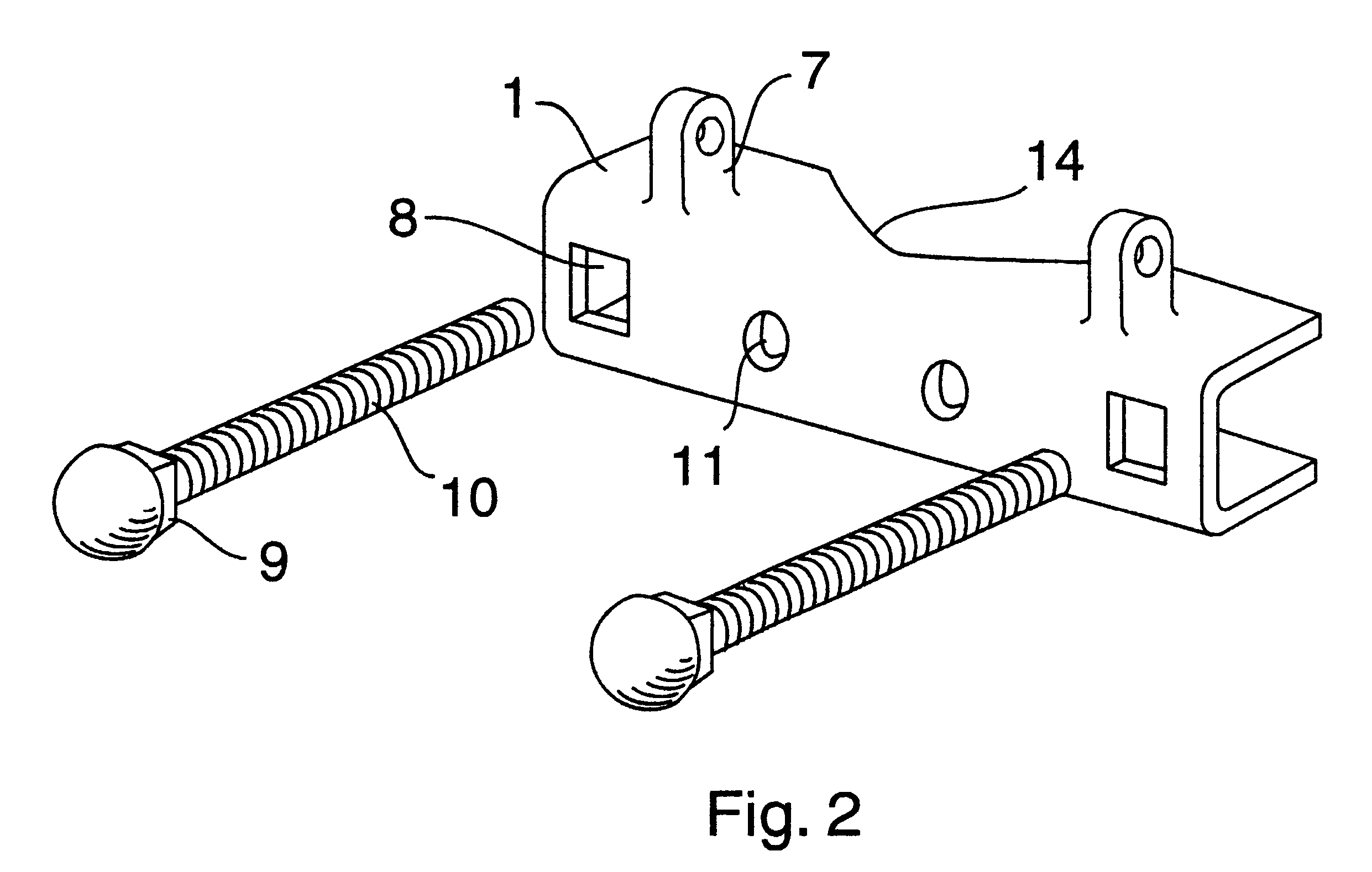
As mentioned above a prior art clamp device comprises a first clamp 1, a base clamp, adapted to be connected to a base, for instance an antenna (not illustrated), for instance by means of screws extending through bores of said first clamp, and adapted to engage an "inner" portion of a pole, a second clamp 2 adapted to engage an "outer" portion of a pole, and two screws 3 adapted to extend through bores 4 and 5 of clamp 1 and clamp 2, respectively and having nuts 6 for tightening the second clamp 1 to the first clamp 2 thereby fixedly mounting the base (antenna) to a pole. Preferably the base clamp 1 can be formed with two lugs 7 or two holes 11 by means of which an antenna can be mounted, for instance tiltable, in relation to the base clamp, of by means of which a coupling box, or a similar means can be connected to the clamp device.

The clamp device according to the invention is basically of the same type as said prior art clamp device shown in FIG. 1.

The clamps 1 and 2 are formed a...


PUM


Abstract

A mounting bracket useful for securing a base, such as an antenna to a pole, a tube or a post, or a similar anchor support, and including a first clamp part, being a base clamp, to be secured to the base (the antenna) adapted to be locked against the pole, and a second clamp part, being tightening clamp, adapted to partly embrace the pole and to be tightened to the base clamp with the pole clamped therebetween, preferably by a screw-nut connection on each side of the pole. The tightening clamp, is formed with two elongated slots extending in the longitudinal direction of the clamp, a first slot of which may be closed and the second slot of which is open at the end of the clamp. The slots having a width matching the diameter of the clamp screws, a length which is at least twice the diameter of the clamp screws and arranged such that the open slot of the tightening clamp can be rotated freely past the corresponding bolt thereby engaging the corresponding clamp screw through the open end of the slot after the pole has been placed in contact with the base clamp. A tightening clamp and a base clamp can be joined in a rotational joint. Thereby an object, which is mounted, e.g. an antenna, can be panned.

Description

The present invention relates to a mounting bracket, whereby is meant a clamp device by means of which an object, for instance an elongated object, an antenna etc, can be secured to a ground pole, a tube or a post, a ground anchored post or a similar anchoring support. The clamp device comprises a first clamp part adapted to be secured to the object to be mounted against the pole, and a second clamp part adapted to embrace the pole and to be tightened to the first clamp part, generally by means of a screw-nut connection means. The invention also relates to a mounting bracket, which alternatively can be used for panning the object if the second clamp part is mounted on a supporting structure such as a wall.BACKGROUND OF THE INVENTION AND RELATED ARTThe invention has basically been developed in connection to mounting of antennas, like a base station or repeater station antenna in a mobile telephone system, whereby said first clamp part is mounted on the antenna while on the ground, wh...

Claims


Application Information

Patent Timeline
Patent Type & Authority Patents(United States)
IPC IPC(8): F16M13/02H01Q1/12
CPCF16M13/02H01Q1/125F16M13/022F16M11/10Y10T403/7188Y10T403/7105
Inventor LILJEVIK, TORD
Owner INTEL CORP
Learn More