
Apparatus for translocating lane divider

a technology for lane dividers and accessories, applied in roadway safety arrangements, roads, construction, etc., can solve the problems of heavy weight and cumbersome lane dividers, excessive wideness of vehicles laterally transporting lightweight lane dividers, and increased curvature of inappropriately placed lightweight lane dividers

Inactive Publication Date: 2001-04-24
QWICK KURB
View PDF11 Cites 63 Cited by
  • Summary
  • Abstract
  • Description
  • Claims
  • Application Information

AI Technical Summary

Problems solved by technology

A first type of lane divider is heavyweight and cumbersome for acting as a barrier.
These heavyweight and cumbersome barriers provided impact resistance in the event that a driver inadvertently steers a vehicle into a lane of oncoming traffic.
Many of these vehicles for laterally transporting the lightweight lane dividers from one lane to another are awkward to use and are extremely wide.
Many of the vehicles for laterally transporting the lightweight lane dividers from one lane to another have certain problems associated with an uneven lateral transfer.
The magnified curvature of the inappropriately placed lightweight lane divider became a driving hazard and had to be manually moved to a correct alignment.
Although the aforementioned vehicles have contributed to the lane divider art, none of the above-mentioned devices solve the problems discussed above which are presently faced in lateral displacement of roadway lane dividers.

Method used


Image

  • Apparatus for translocating lane divider
  • Apparatus for translocating lane divider
  • Apparatus for translocating lane divider

Examples


first embodiment

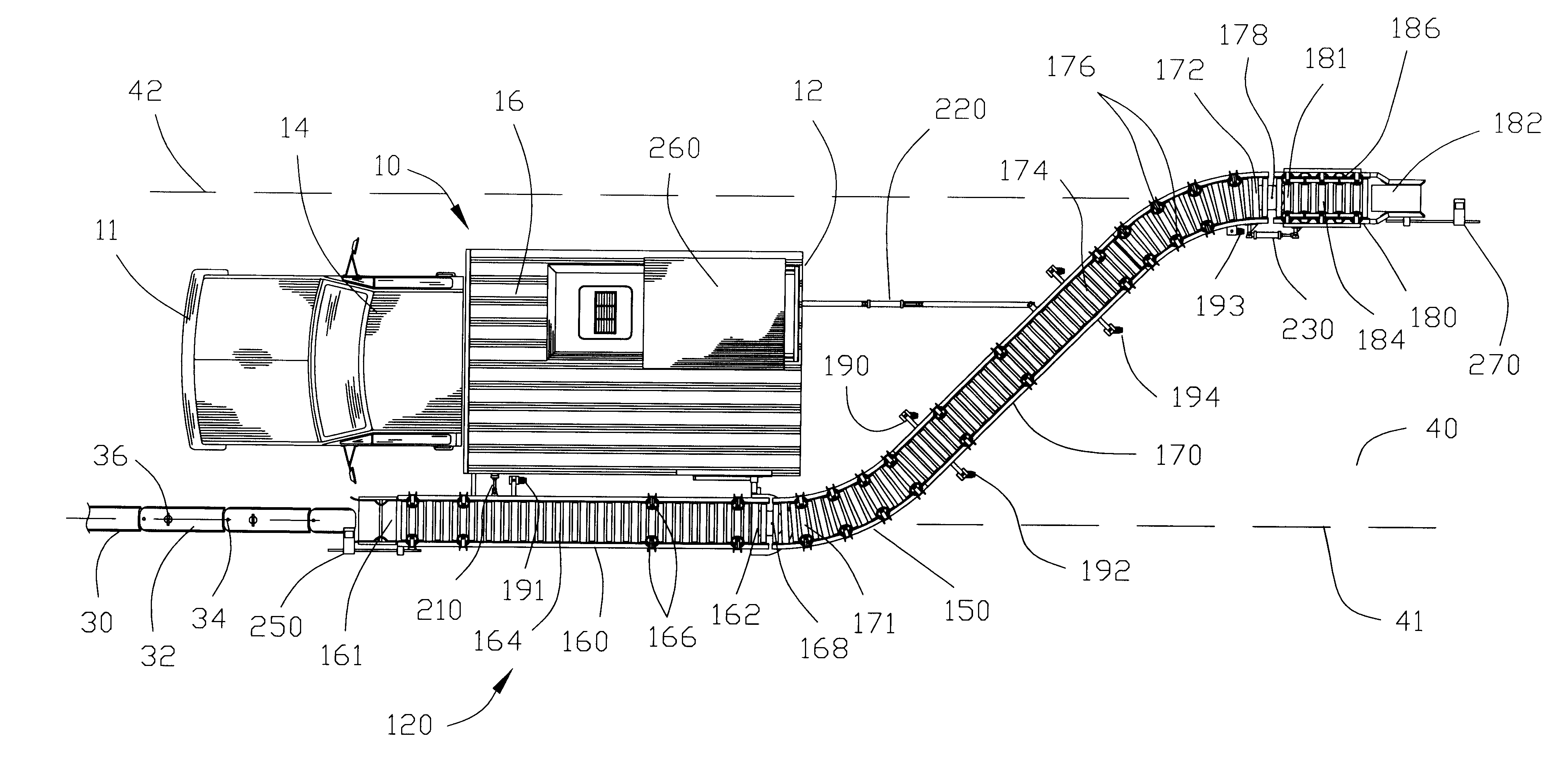
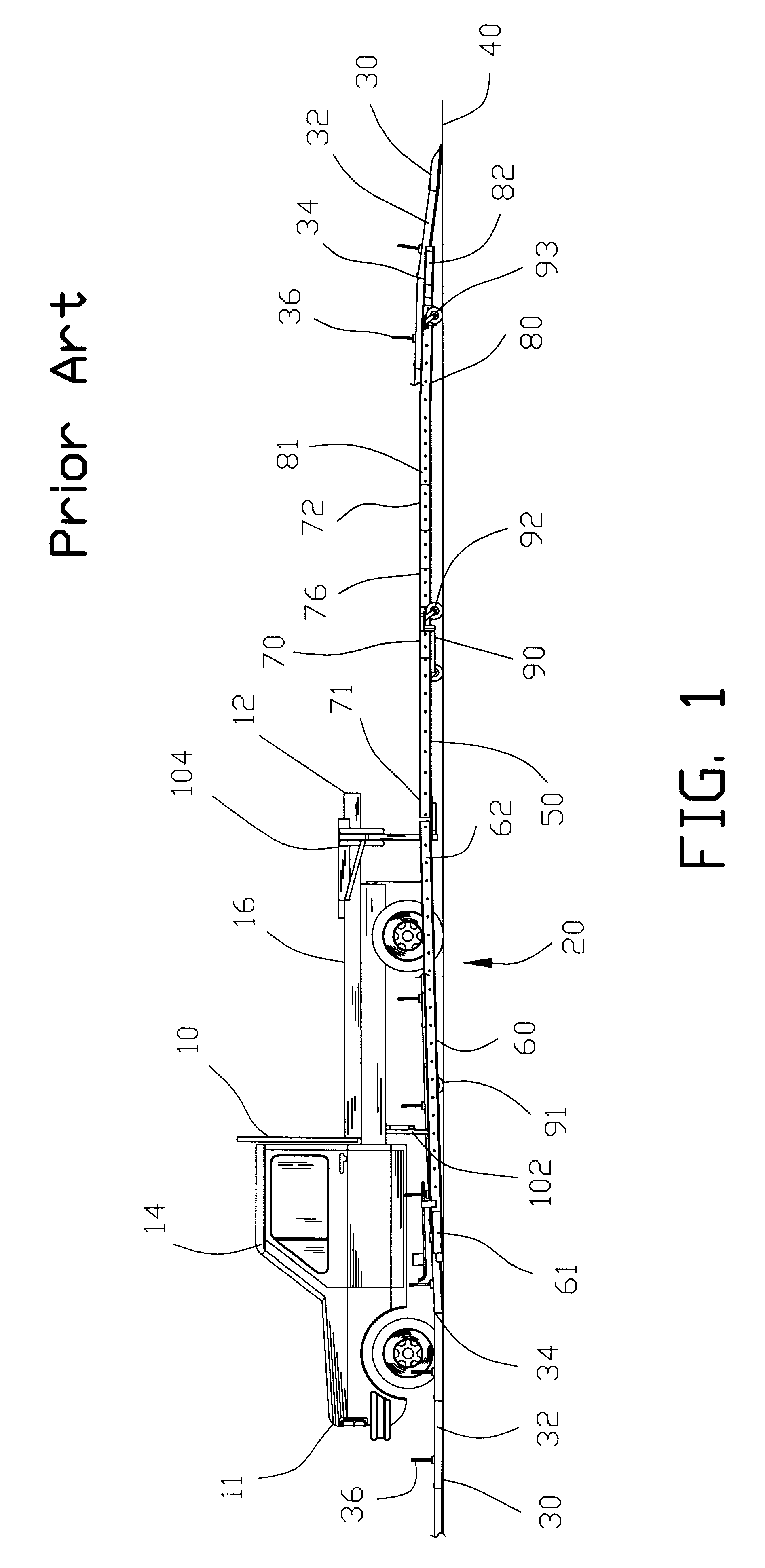
FIGS. 4 and 5 are side and top views of the apparatus 120 for laterally translocating the lane dividers 30 incorporating the present invention. The apparatus 120 comprises a generally serpentine-shape conveyor 150 having a receiving segment 160, a translocating segment 170 and a discharge segment 180. The receiving segment 160 extends between an input end 161 and an output end 162. A plurality of horizontally disposed rollers 164 are located on the receiving segment 160. A plurality of angularly disposed rollers 166 are disposed on opposed sides of the plurality of horizontally disposed rollers 164. The plurality of horizontally disposed rollers 164 and the plurality of angularly disposed rollers 166 assisting the movement of the lane dividers 30 thereupon.

The translocating segment 170 extends between an input end 171 and an output end 172. A plurality of horizontally disposed rollers 174 are located on the translocating segment 170. A plurality of angularly disposed rollers 176 are...

second embodiment

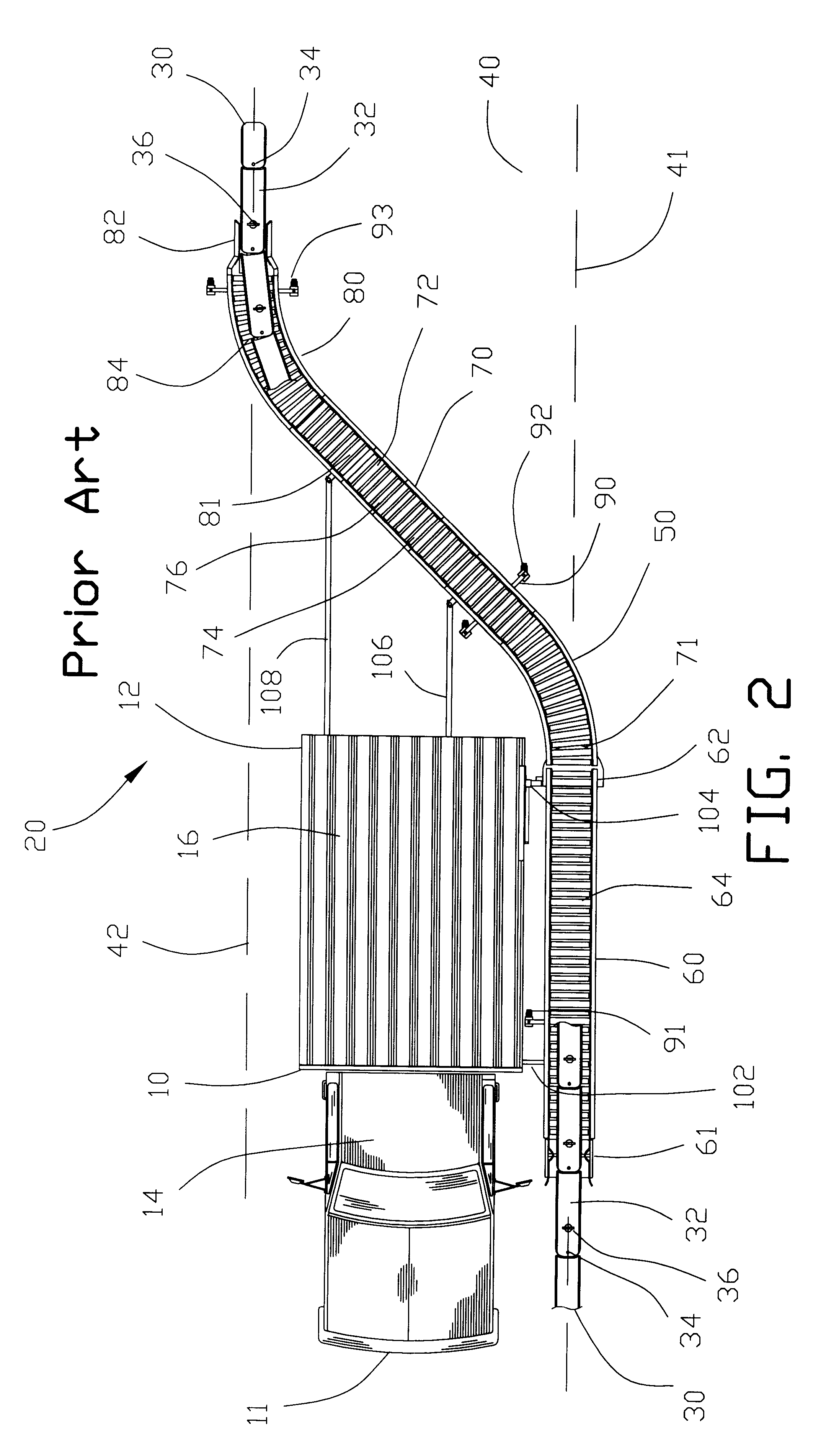
the present invention shown in FIG. 13 provides an apparatus 320 for laterally translocating the lane divider 30 from an initial position 41 to final position 41 on a roadway 40 wherein the final position 41 is aligned in the same lane as the initial position on the roadway 40. The second embodiment of the present invention provides an apparatus for aligning misaligned lane dividers 30 on a roadway 40.


PUM


Abstract

An apparatus and method is described for translocating a lane divider from an initial position to a final position on a roadway. The apparatus comprises a conveyor connected to a vehicle. The conveyor includes a receiving segment for receiving the lane divider from the initial position on the roadway and a discharging segment for discharging the lane divider to the final position on the roadway. The receiving segment and the discharging segment are pivotally connected relative to one another. The receiving segment may be pivoted to enable the lateral movement of the receiving segment to accommodate for variation in the initial position of the lane divider on the roadway. The discharging segment may be pivoted for discharging the lane divider to a final position aligned on the roadway. A translocating segment may be interposed between the receiving segment and the discharging segment for moving the lane divider from one lane to another lane on the roadway.

Description

1. Field of the InventionThis invention pertains to lane dividers for roadways and more specifically, to an apparatus and method for laterally translocating lane dividers from one position on a roadway to another. The apparatus and method may be used for adjusting the position of the lane dividers on the roadway or may be used for moving the lane dividers from one lane to another lane on the roadway.2. Background of the InventionLane dividers are presently utilized in a number of roadway applications. Most commonly, lane dividers are utilized in road construction and alter the number of lanes extending to and from urban areas on a multiple lane highway depending on the time of day and anticipated traffic flow.For example, in a six-lane roadway, four lanes will be utilized to transport traffic into an urban area during morning hours. The other two lanes will be utilized to transport traffic out of the urban area. During the evening hours, four lanes will be used to transport traffic ...

Claims


Application Information

Patent Timeline
IPC IPC(8): E01F9/014E01F9/04E01F9/011E01F15/00E01F9/093E01F9/594E01F9/70E01F13/00
CPCE01F9/014E01F9/093E01F15/006E01F9/70E01F9/594
Inventor SCHINDLER, ROBERT J.DOUBERLY, MARSHALL L.
Owner QWICK KURB
Learn More