
Circuit continuity detection system and method

a continuity detection and circuit technology, applied in the field of circuit continuity detection system and method, can solve the problems of inability to arbitrate between conventional devices, cost, cumbersome method,

Inactive Publication Date: 2001-02-20
IBM CORP
View PDF17 Cites 16 Cited by
  • Summary
  • Abstract
  • Description
  • Claims
  • Application Information

AI Technical Summary

Problems solved by technology

However, this only provides information while the circuit is in the process of operating.
Conventional devices provide no such means to arbitrate the presence of current in a circuit along with the voltage request or demand for power.
However, this method is costly, cumbersome and requires externally-powered devices.
Further, its distributed nature makes it a formidable challenge to implement.

Method used


Image

  • Circuit continuity detection system and method
  • Circuit continuity detection system and method
  • Circuit continuity detection system and method

Examples


Embodiment Construction

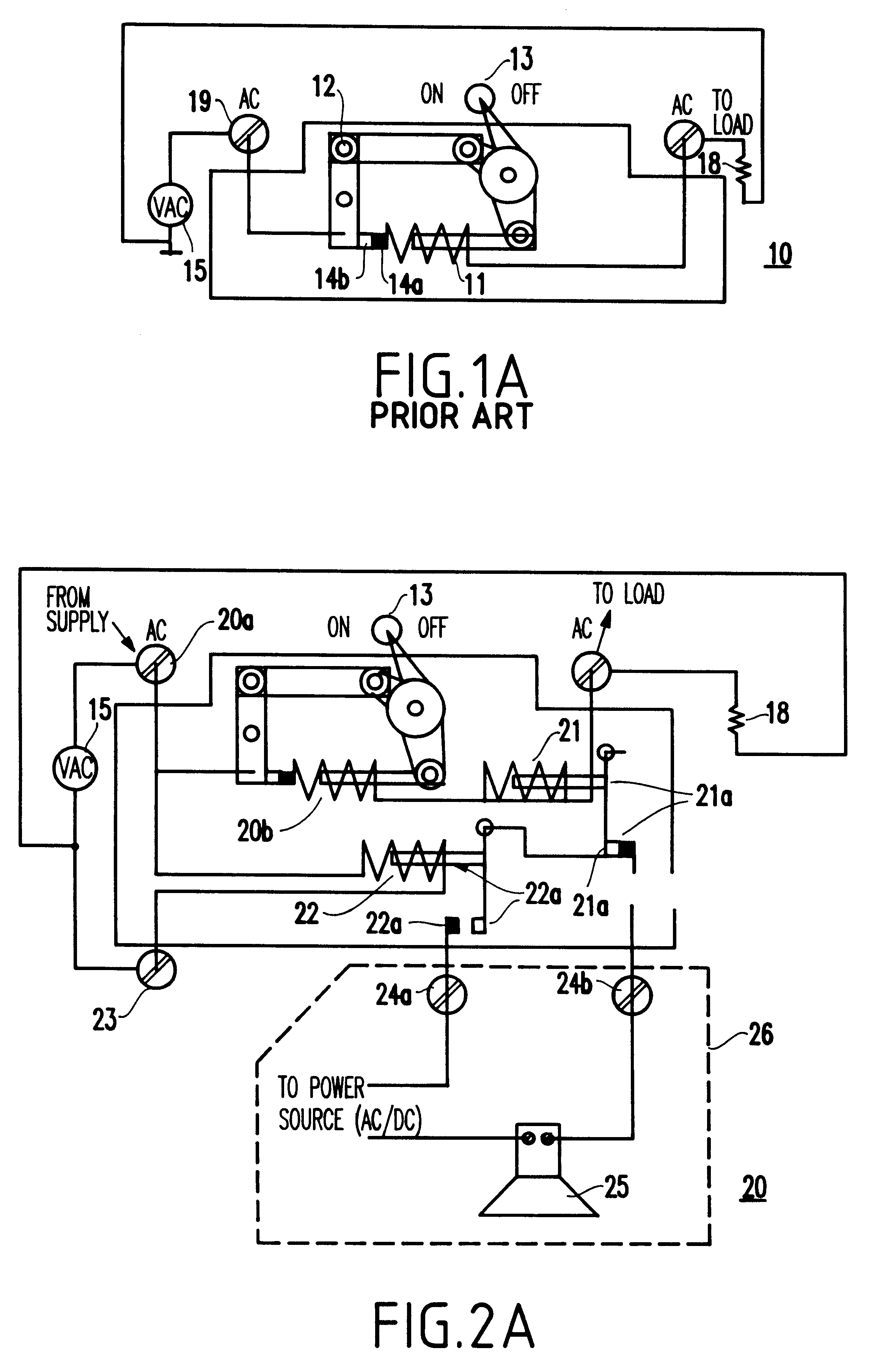
Referring to FIGS. 2A, 2B, 2C, and 3, preferred embodiments of the present invention will be described herein below.

Generally, the present inventors have found that a solution to the above mentioned problems of the conventional structure is to utilize existing circuit hardware and maintain the existing circuit layout to minimize breaks in the circuit and to localize the data input / output.

In a basic application, the present invention provides a circuit breaker (and method) that includes a current sensing coil, a voltage reference (e.g., to ground) sensing coil, and an arbitration means to reconcile the signals indicated from the coils (e.g. logical "AND" of coil contacts). For example, current sensed would indicate that the circuit is functioning properly. In a situation where no current is sensed and voltage is sensed, it would be determined that the circuit element is open or that the circuit breaker has tripped. In a situation where no current was sensed and no voltage is sensed, ...


PUM


Abstract

In many technical applications, situations often arise where it is desirable to know, in real time, if a circuit is functioning. That is, it is desirable to know if, for example, a heater element is operational or blown (open). By sensing the current flowing to the circuit, it is easy to determine if the circuit is operational. However, this only provides information while the circuit is in the process of operating. There must be some real-time connection with the request or demand for power to know if in fact the device is non-operational, or if there is simply no controller request for power. A system (and method) according to the invention includes a real-time, simultaneous current and voltage sensing and arbitration device which provides a single, point of use implementation, and allows for detection and signaling of a fault condition. A circuit breaker may be constructed to incorporate such a system.

Description

1. Field of the InventionThe present invention generally relates to a circuit continuity detection system and method, and more specifically, to a circuit continuity detection system and method that senses current and voltage simultaneously at a single point of operation.2. Description of the Related ArtIn many technical applications, situations often arise where it is desirable to know, in real time, if a circuit is functioning. That is, it is desirable to know if, for example, a heater element is operational or "blown" (open). It is relatively simple to determine if the circuit is operational by sensing the current flowing to the circuit.However, this only provides information while the circuit is in the process of operating. There must be some real-time relation to or connection with the request or demand for power, to determine if the device is in fact not operational, or if there is simply no controller request to provide power. Conventional devices provide no such means to arbi...

Claims


Application Information

Patent Timeline
Patent Type & Authority Patents(United States)
IPC IPC(8): G01R31/02
CPCG01R31/026G01R31/52G01R31/54
Inventor HANSEN, MARKKATZ, ROBERT PAUL
Owner IBM CORP
Learn More