Coating method and apparatus

a coating apparatus and coating technology, applied in the field of coating methods and apparatuses, can solve the problems of excessive wide web, drop in yield, and above-mentioned coating apparatuses cannot coat the web satisfactorily

Inactive Publication Date: 2000-11-14
FUJIFILM HLDG CORP +1
View PDF5 Cites 16 Cited by
  • Summary
  • Abstract
  • Description
  • Claims
  • Application Information

AI Technical Summary

Problems solved by technology

Furthermore, the above-mentioned coating apparatuses cannot coat the web satisfactorily if the web takes a winding course, because the guide plates 103 are fixed.
To apply the coating liquids on the web that is taking a winding course in the conventional coating apparatus, there is no other way but to use an excessively wide web to leave uncoated areas with proper widths at both edge regions of the web.
The edge regions of the web must be cut off after the coating, which drops the yield.

Method used


Image

  • Coating method and apparatus
  • Coating method and apparatus
  • Coating method and apparatus

Examples


example 1

The test for confirming the effects of the present invention was conducted by using the slide coating apparatus in FIG. 10.

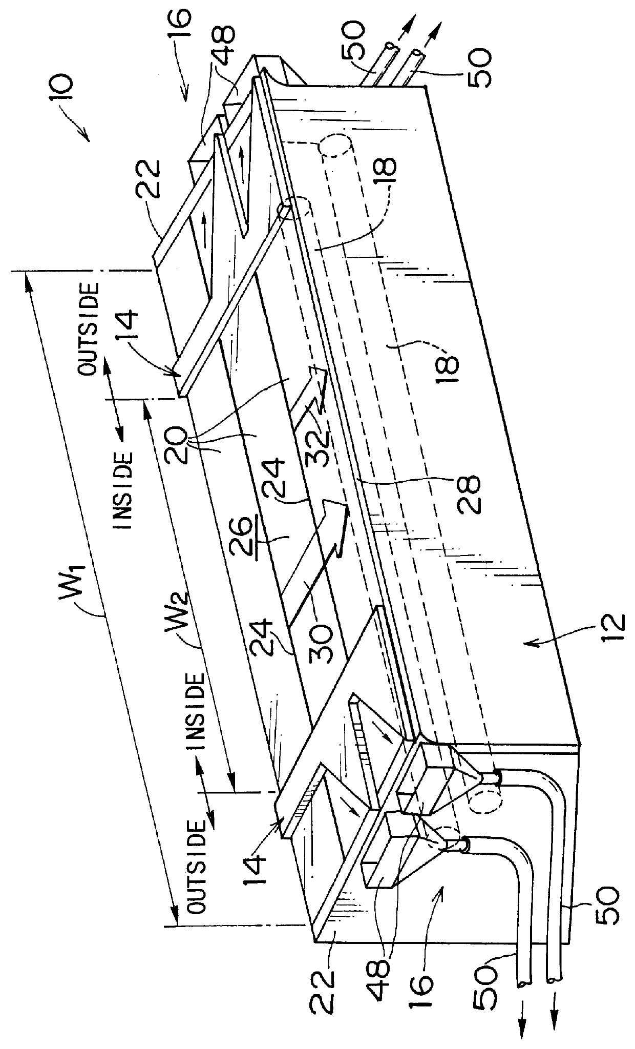
First, the pair of guide members 14 were set in such a manner that the regulated width W.sub.2 of the coating liquids is 400 mm in conformity with the web of 400 mm width. In this state, the slide coating apparatus was run, and the coated state of the web was observed. Next, the web width was changed from 400 mm to 300 mm without stopping the coating apparatus. To change the web width, the trailing end of the 400 mm wide web was spliced to the leading end of the 300 mm wide web.

The coating conditions were as follows:

1) the type of web: a hydrophilicized aluminum support

2) the width of a slit in the coating hopper (the liquid supply width): 600 mm

3) the coating speed: 20 m / min

4) the length of a coating dry line: 150 m

5) the type of a coating liquid for the lower layer of two layers: polyvinyl alcohol solution (20 cps, 32 dyne / cm, 1.024 g / cm.sup.3)

6) the type of a...

example 2

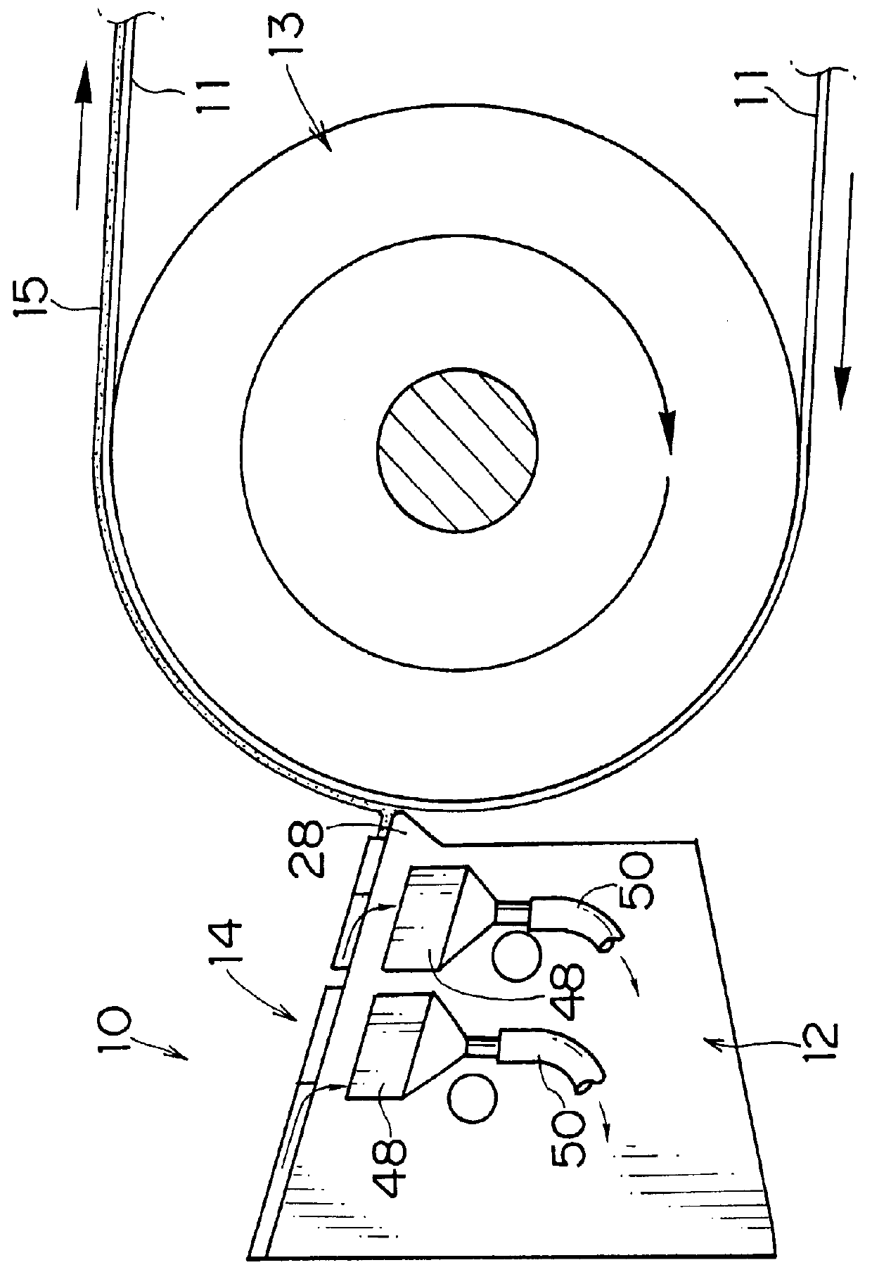
The web was made to take a winding course with displacement along the width by 10 mm, and the slide coating apparatus performed the continuous coating under the conditions of the example 1. The second slide device 56 was operated to slide the coating hopper 12 in accordance with the displacement of the web.

As a result, the coating hopper 12 was moved to follow the displacement of the web of 10 mm, which enabled the continuous coating without leaving any uncoated areas at the edge regions of the web.

As set forth hereinabove, according to the coating method and apparatus of the present invention, the width of the coating liquids can be adjusted without stopping the coating apparatus when there is a change in the web width.

Moreover, there is no necessity for inserting the pocket stoppers and the spacers to the manifolds and the slits to regulate the widths of the manifolds and the slits, and hence, it is unnecessary to change the amount of the coating liquids supplied to the manifolds ...


PUM

PropertyMeasurementUnit
widthaaaaaaaaaa
widthaaaaaaaaaa
widthaaaaaaaaaa

Abstract

Coating liquids are supplied to a coating hopper, and are extruded onto a slide surface of the coating hopper through slits. A pair of guide members are provided at both sides of the slide surface. Side faces of the guide members are positioned at both ends of a desired width of the coating liquids flowing of the slide surface to be applied on a traveling web. Consequently, the coating liquids that flow over the whole width of the slits are divided into the inside and the outside of the desired width by the guide members, and the divided coating liquids are extruded onto the slide surface. The coating liquids within the desired width flow down between the guide members and coat the web, whereas the coating liquids outside the desired width are collected through channels, which are formed in the guide members.

Description

1. Field of the InventionThe present invention relates generally to a coating method and apparatus, and more particularly to a coating method and apparatus for coating a continuously-traveling web with coating liquids flowing down a slide surface of a coating hopper in manufacturing photographic film, photographic printing paper, magnetic recording tape, adhesive tape, pressure sensitive paper, offset printing plates, batteries, and so forth.2. Description of Related ArtA slide bead coating apparatus is an example of coating apparatuses for applying coating liquids on the surface of a continuously-traveling web. U.S. Pat. No. 2,761,791 of Russell discloses a multilayer slide bead coating apparatus. According to this apparatus, a plurality of coating liquids flowing down a slide surface form beads in a gap where the coating liquids meet the traveling web, and the coating liquids are applied to the surface of the web through the beads.There is also a curtain coating apparatus that coa...

Claims


Application Information

Patent Timeline
Patent Type & Authority Patents(United States)
IPC IPC(8): B05C5/00B05C11/10G03C1/74B05C9/00B05C9/06B05D1/30B05C1/04B05C3/172B05C5/02
CPCB05C5/007B05C5/008B05C11/1039G03C1/74B05C9/06Y10S118/04G03C2001/7481G03C2001/7492
Inventor KAMITANI, KIYOSHI
Owner FUJIFILM HLDG CORP
Why Eureka
Try Eureka