Bow-mounted chronograph

a chronograph and bow-mounted technology, applied in the field of bow-mounted chronographs, can solve the problems of only being able to conveniently measure the velocity of the arrow, and the method can be very inaccura

Inactive Publication Date: 2000-02-22
INNOVENTIVE TECH & SERVICES
View PDF9 Cites 41 Cited by
  • Summary
  • Abstract
  • Description
  • Claims
  • Application Information

AI Technical Summary

Problems solved by technology

This method can be very inaccurate since the falling target must be released at the precise moment the arrow is loosed from the bow.
As with the first technique, arrow velocity can only be conveniently measured while the arrow is released towards a stationary target with die measuring device placed in a predetermined position.

Method used


Image

  • Bow-mounted chronograph
  • Bow-mounted chronograph
  • Bow-mounted chronograph

Examples


Embodiment Construction

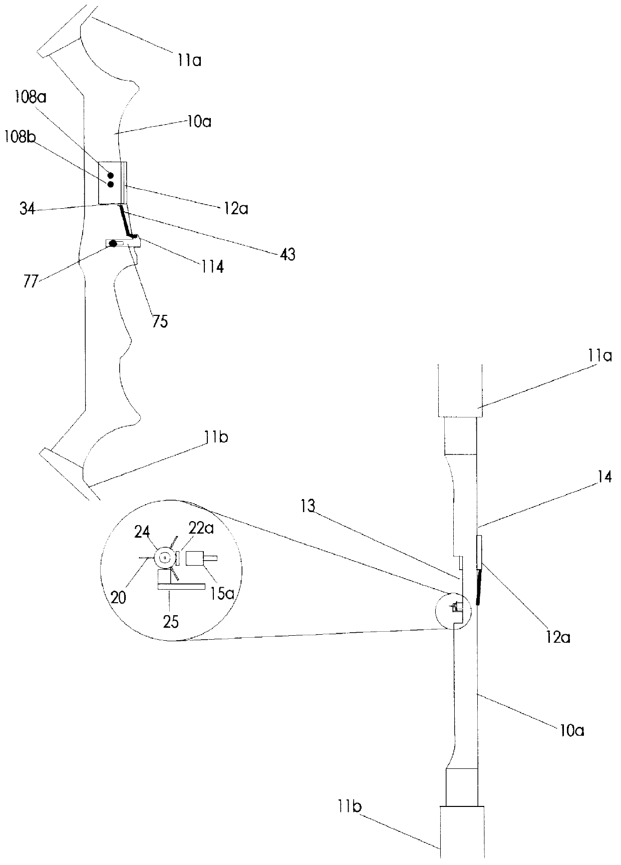
A perspective view of a bow-mounted chronograph measurement unit is illustrated in FIG. 3. The bow-mounted chronograph measurement unit is a battery-powered electronic circuit that is designed to be mounted external to a bow riser. The chronograph measurement unit can display statistical parameters of collected data through a user-selectable interface.

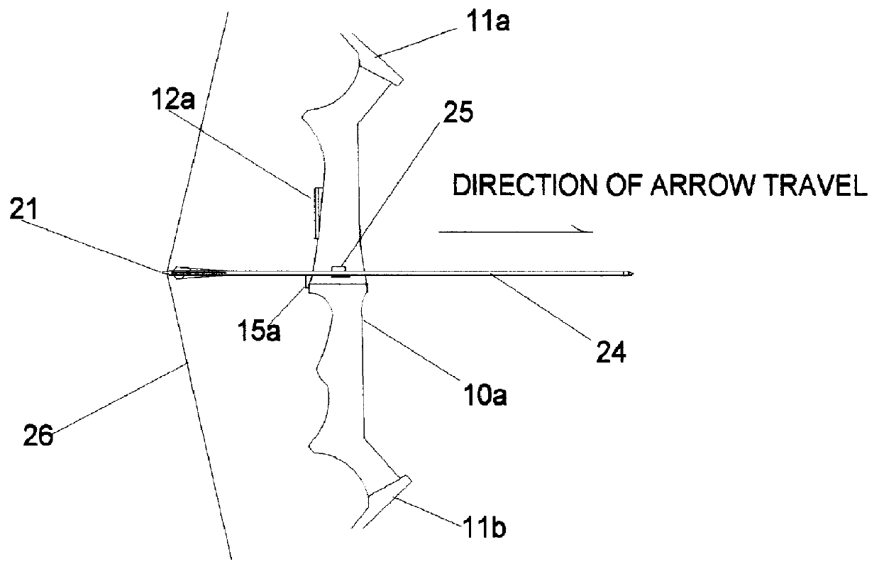
All structural features are illustrated in FIG. 3. The bow-mounted chronograph measurement unit 12a is comprised of an injection molded plastic housing assembly 57, a bezel 53a, a display lens 53b and a chronograph electronics assembly 35. The chronograph measurement unit or assembly also includes a magnetic sensor 15a that is responsive to the presence of a magnet field. Magnetic sensor 15a is a commercially available, latching magnetic sensor with a Schmitt Trigger output. A sensor cable-connector assembly 43 connects a voltage source 42 to magnetic sensor 15a. Magnetic sensor 15a output is connected to a chronograph measurement unit...


PUM


Abstract

A instrument and method for measuring archery tackle performance is disclosed. A low power, electronics measurement unit attached onto or mounted internal to a bow in communication with a sensor which detects a signal from an external trigger mechanism mounted onto or internal to an arrow shaft for the purposes of measuring arrow velocity or collecting data indicative of arrow position. The statistical parameters of the collected data may then be used to determine and improve archery tackle performance in any shooting situation.

Description

1. Field of InventionThis invention relates to archery equipment, specifically to an improved method of measuring arrow velocity or arrow position.2. Description of Prior ArtPreviously, arrow velocity was determined by placing a complex mechanical apparatus adjacent to a stationary target. One such invention is described in U.S. Pat. No. 3,401,334. To measure arrow velocity, a moveable target released from the apparatus would fall in the arrow path down the surface of the stationary target. As the arrow strikes die stationary target, the moving target is pinned to the stationary target. By knowing the moveable target's relationship with respect to gravity, the measured distance it fell, and the distance the arrow traveled, arrow velocity could be calculated. This method can be very inaccurate since the falling target must be released at the precise moment the arrow is loosed from the bow.As the state of the ar in electronics advanced, independent or stand-alone chronographs were dev...

Claims


Application Information

Patent Timeline
Patent Type & Authority Patents(United States)
IPC IPC(8): F41B5/00F41B5/14G01P3/64G01P3/66
CPCF41B5/14G01P3/66F41B5/1484
Inventor DILGER, JOHN PATRICK
Owner INNOVENTIVE TECH & SERVICES
Why Eureka
Try Eureka