Venting Unit and Housing, in Particular Battery Housing

Pending Publication Date: 2022-10-27
MANN HUMMEL GMBH
View PDF0 Cites 0 Cited by
  • Summary
  • Abstract
  • Description
  • Claims
  • Application Information

AI Technical Summary

Benefits of technology

The invention provides a venting unit for a housing, particularly a battery, that quickly reduces pressure when there is an excess of pressure in the housing. This helps to prevent damage to the battery and other components in the housing. The purpose of the invention is to offer a safer and effective solution for managing pressure in battery housings.

Problems solved by technology

In addition, in particular in battery housings, an emergency venting function must be present for sudden pressure increase due to failure of the battery cells.

Method used


Image

  • Venting Unit and Housing, in Particular Battery Housing
  • Venting Unit and Housing, in Particular Battery Housing
  • Venting Unit and Housing, in Particular Battery Housing

Examples


Embodiment Construction

[0055]In the Figures, same or same-type components are identified with same reference characters. The Figures show only examples and are not to be understood as limiting.

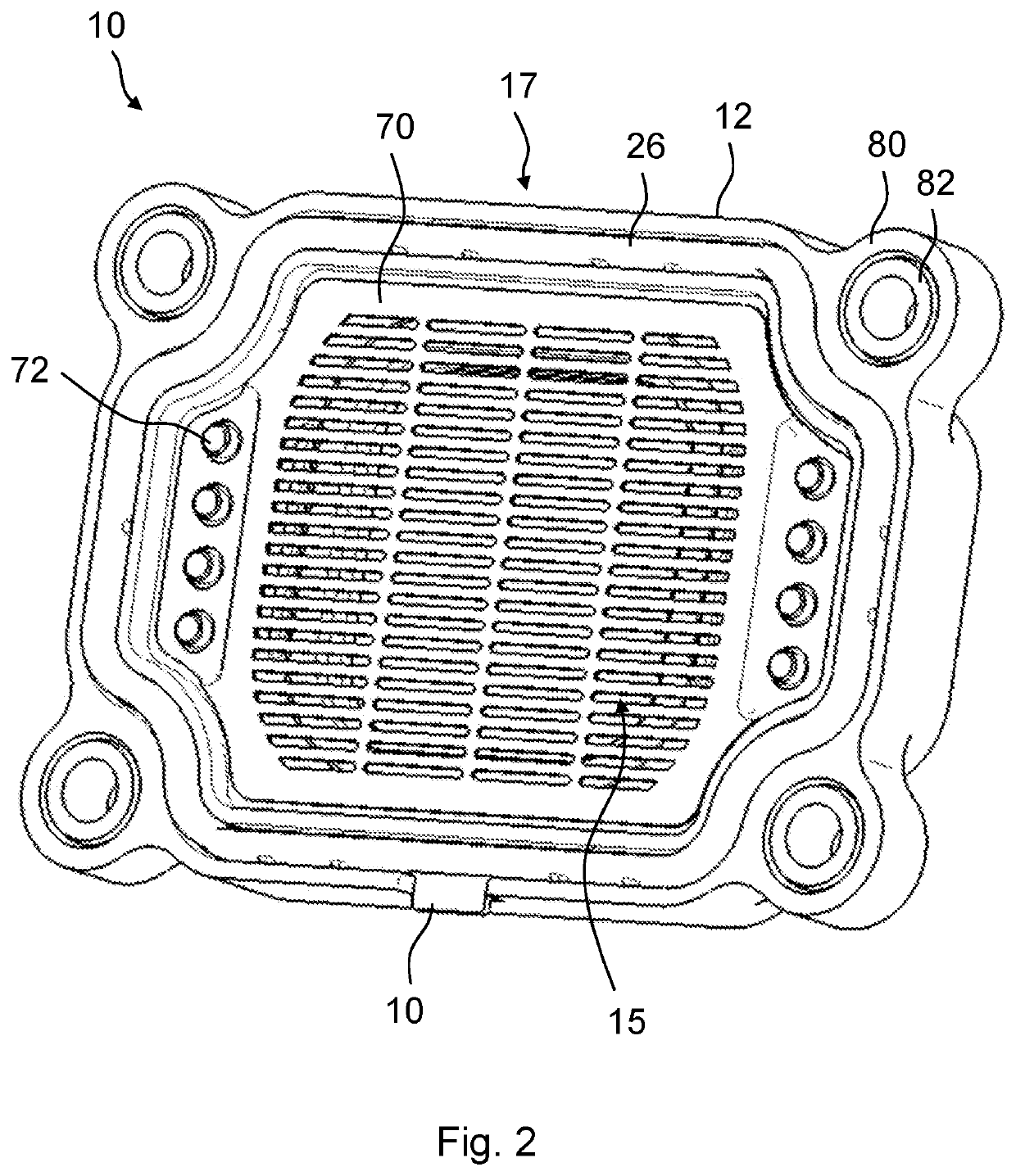
[0056]FIG. 1 shows an isometric view of a venting unit 10 for a housing 20, in particular of a battery, in particular of a traction battery of a motor vehicle, according to an embodiment of the invention from an exterior side 18 while in FIG. 2 an isometric view of the venting unit 10 from an inner side 17 can be seen. FIG. 3 shows the isometric view of the venting unit 10 from the inner side 17 with removed protective grid 70.

[0057]Details of the venting unit 10 can be seen in FIG. 4 with an isometric section view with half-sectioned base body 12 as well as in FIG. 5 with an isometric section view with sectioned seal 32, In FIG. 6, a longitudinal section of the venting unit 10 is illustrated. FIG. 7 shows in this context an enlarged longitudinal section of the venting unit 10 in the region of the clamping action of...


PUM


Abstract

A venting unit for a housing has a base body to be connected fluid-tightly to an edge of a housing opening of the housing. The base body has an exterior side and an inner side. The base body has a gas passage opening and a rim surrounding it. A membrane areally spans the gas passage opening transversely to an axial direction of the base body. The membrane is connected fluid-tightly to the base body at the rim of the base body and is arranged at the inner side of the base body. A clamping frame is connected to the base body at the inner side in a region radially outside of the rim of the base body. The clamping frame has a circumferentially extending clamping surface exerting a clamping force on the membrane to hold the membrane with friction fit between clamping frame and rim of the base body.

Description

BACKGROUND OF THE INVENTION[0001]The invention concerns a venting unit for a housing, in particular of a battery, in particular of a traction battery of a motor vehicle, as well as a housing, in particular a battery housing.[0002]Housings for receiving electronic components such as, for example, battery cells and the like, cannot be closed off completely gas-tightly relative to the environment. On the one hand, due to temperature fluctuations, for example, due to heat introduction during charging or discharging of battery cells, and, on the other hand, due to naturally occurring air pressure fluctuations, in particular in mobile systems, a gas exchange between interior and exterior must be enabled. Due to the gas exchange, impermissible mechanical loads of the housing, in particular bursting or bulging of the housing, can be prevented. In addition, in particular in battery housings, an emergency venting function must be present for sudden pressure increase due to failure of the batt...

Claims


Application Information

Patent Timeline
IPC IPC(8): H01M50/30H01M50/342
CPCH01M50/394H01M50/3425H01M2200/20H01M50/244H01M50/249Y02E60/10
Inventor SCHLEIDEN, THOMASWINGER, OLIVERPLOPPA, MARTIN
Owner MANN HUMMEL GMBH
Why Eureka
Try Eureka