Power over fiber system and feed light visualization lid member

a fiber optic system and feed light technology, applied in the field of optical power supplies, can solve problems such as injuries or accidents of users, users or the like cannot determine easily whether feed light is being released to the outside, and achieve the effect of reducing the risk of injuries or accidents

Pending Publication Date: 2022-07-28
KYOCERA CORP
View PDF0 Cites 0 Cited by
  • Summary
  • Abstract
  • Description
  • Claims
  • Application Information

AI Technical Summary

Problems solved by technology

By the way, if invisible light beams are used as feed light, a user or the like cannot easily determine whether the feed light is being released to the outside.
An optical power supply system using a high-power laser for power supply may cause injuries or accidents by a user or the like handling an optical fiber or another module thereof without being aware of release of feed light.

Method used


Image

  • Power over fiber system and feed light visualization lid member
  • Power over fiber system and feed light visualization lid member
  • Power over fiber system and feed light visualization lid member

Examples


first embodiment

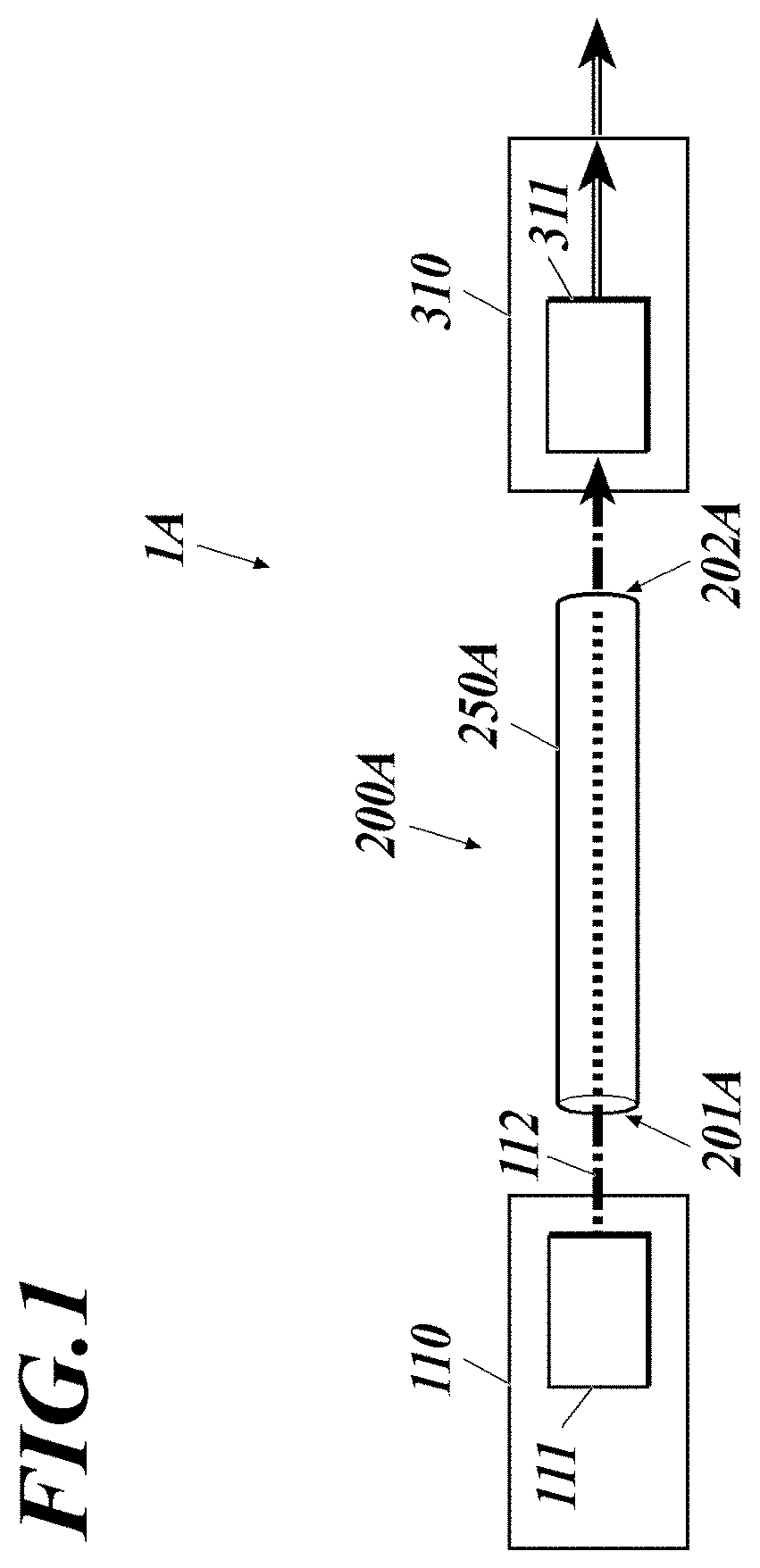
[0023]As shown in FIG. 1, a power over fiber (PoF) system 1A of this embodiment includes a power sourcing equipment (PSE) 110, an optical fiber cable 200A and a powered device (PD) 310.

[0024]In the present disclosure, a power sourcing equipment converts electric power into optical energy and supplies (sources) the optical energy, and a powered device receives (draws) the supplied optical energy and converts the optical energy into electric power.

[0025]The power sourcing equipment 110 includes a semiconductor laser 111 for power supply.

[0026]The optical fiber cable 200A includes an optical fiber 250A that forms a transmission path of feed light.

[0027]The powered device 310 includes a photoelectric conversion element 311.

[0028]The power sourcing equipment 110 is connected to a power source, and electrically drives the semiconductor laser 111 and so forth.

[0029]The semiconductor laser 111 oscillates with the electric power from the power source, thereby outputting feed light 112.

[0030]...

second embodiment

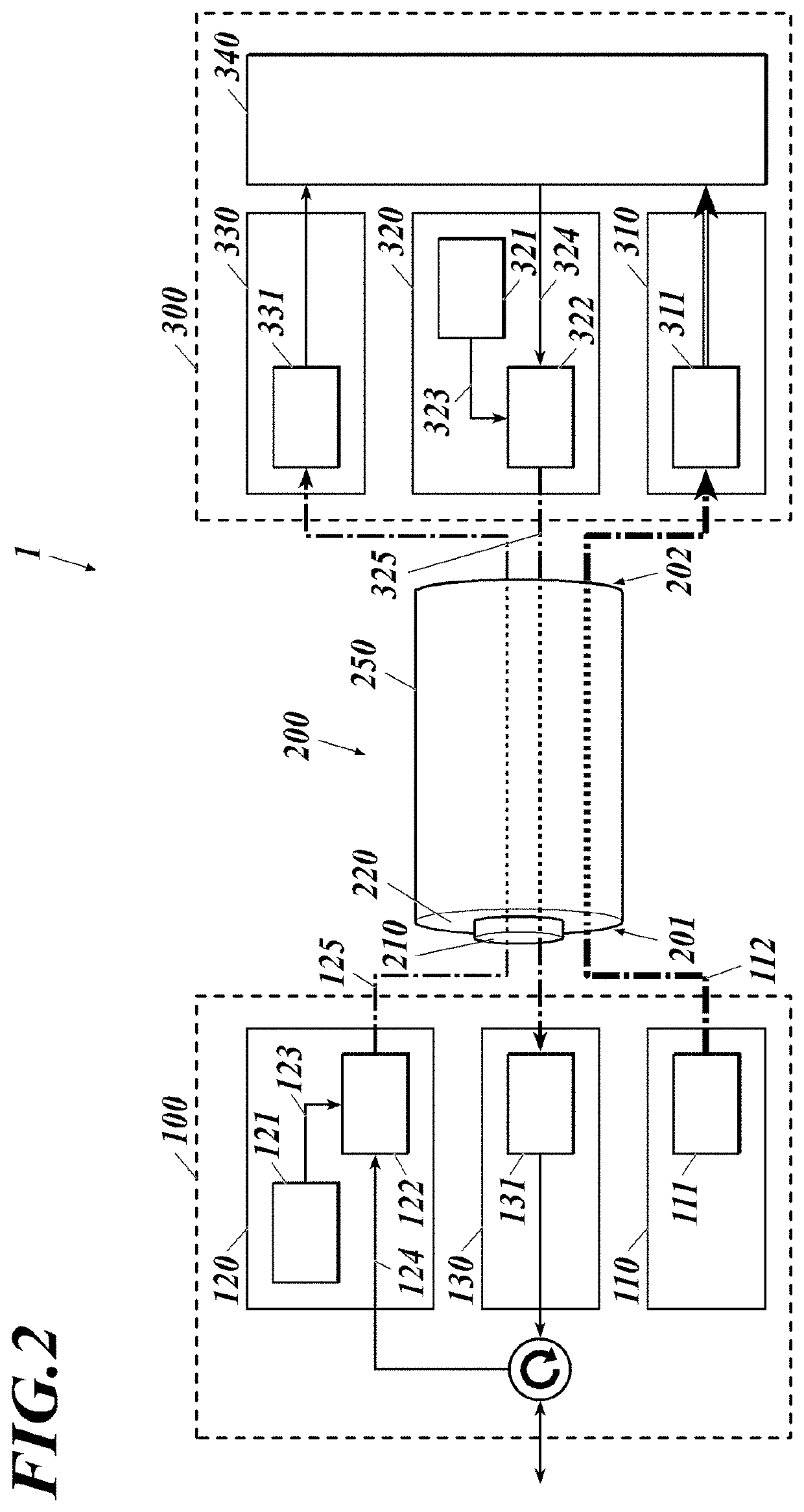
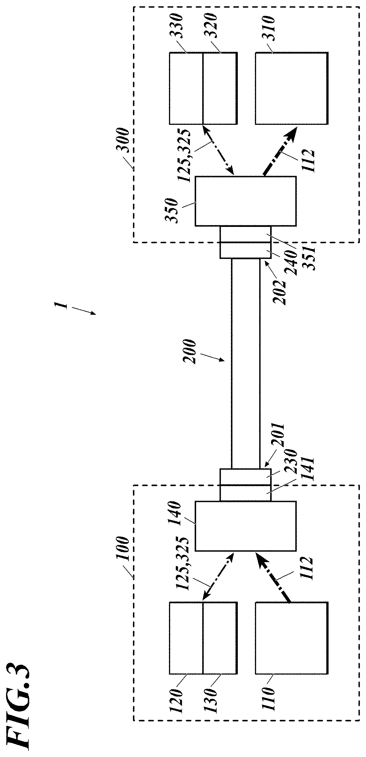
[0040]As shown in FIG. 2, a power over fiber (PoF) system 1 of this embodiment includes a power supply system through an optical fiber and an optical communication system therethrough, and includes: a first data communication device 100 including a power sourcing equipment (PSE) 110; an optical fiber cable 200; and a second data communication device 300 including a powered device (PD) 310.

[0041]The power sourcing equipment 110 includes a semiconductor laser 111 for power supply. The first data communication device 100 includes, in addition to the power sourcing equipment 110, a transmitter 120 and a receiver 130 for data communication. The first data communication device 100 corresponds to a data terminal equipment (DTE), a repeater or the like. The transmitter 120 includes a semiconductor laser 121 for signals and a modulator 122. The receiver 130 includes a photodiode 131 for signals.

[0042]The optical fiber cable 200 includes an optical fiber 250 including: a core 210 that forms a...


PUM

PropertyMeasurementUnit
wavelengthaaaaaaaaaa
poweraaaaaaaaaa

Abstract

A power over fiber system includes a power sourcing equipment, a powered device, an optical fiber cable and an openable/closeable or attachable/detachable lid member. The power sourcing equipment includes a semiconductor laser that oscillates with electric power, thereby outputting feed light. The powered device includes a photoelectric conversion element that converts the feed light output by the power sourcing equipment into electric power. The optical fiber cable transmits the feed light from the power sourcing equipment to the powered device. The feed light is invisible light. The lid member covers an outgoing portion from which the feed light goes out. At least part of a light receiving portion of the lid member, the light receiving portion receiving the feed light, is made of a wavelength conversion material that converts a wavelength of the feed light into a wavelength of visible light.

Description

RELATED APPLICATIONS[0001]The present application is a National Phase of International Application No. PCT / JP2020 / 020616 filed May 25, 2020, which claims priority to Japanese Application No. 2019-105978, filed Jun. 6, 2019.TECHNICAL FIELD[0002]The present disclosure relates to optical power supply.BACKGROUND ART[0003]Recently, there has been studied an optical power supply system that converts electric power into light (called feed light), transmits the feed light, converts the feed light into electric energy, and uses the electric energy as electric power.[0004]There is disclosed in Patent Literature 1 an optical communication device that includes: an optical transmitter that transmits signal light modulated with an electric signal and feed light for supplying electric power; an optical fiber including a core that transmits the signal light, a first cladding that is formed around the core, has a refractive index lower than that of the core, and transmits the feed light, and a secon...

Claims


Application Information

Patent Timeline
Patent Type & Authority Applications(United States)
IPC IPC(8): H02J50/30H04B10/80H04B10/50
CPCH02J50/30H04B10/503H04B10/80H04B10/807
Inventor TETSUKA, NOBUYUKI
Owner KYOCERA CORP
Why Eureka
Try Eureka