
Lidar

a laser detection and laser technology, applied in the field of laser detection, can solve the problems of high production cost, complex structure of lasers, inconvenient disassembly,

Pending Publication Date: 2022-07-21
SUTENG INNOVATION TECH CO LTD
View PDF0 Cites 6 Cited by
  • Summary
  • Abstract
  • Description
  • Claims
  • Application Information

AI Technical Summary

Benefits of technology

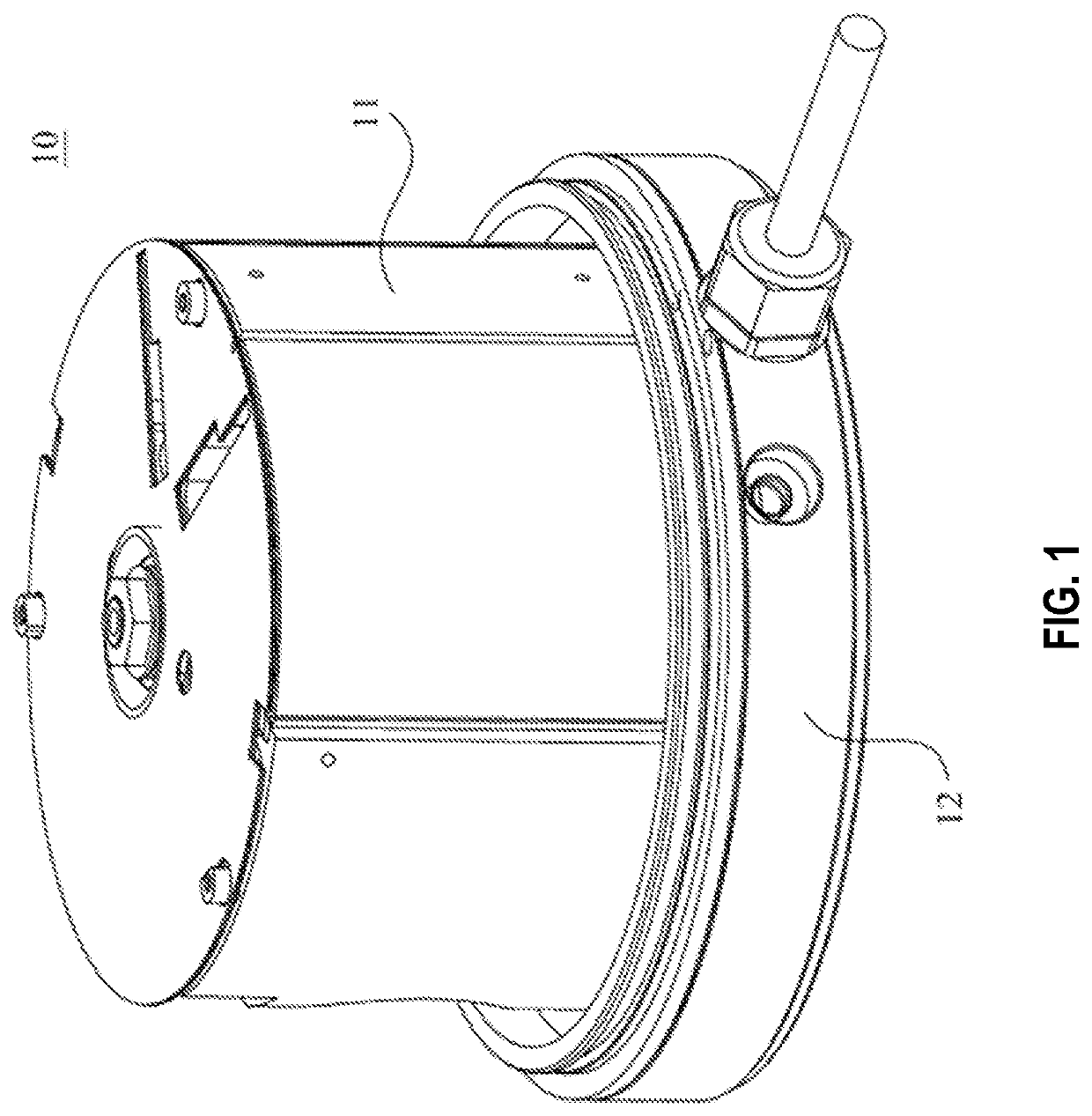
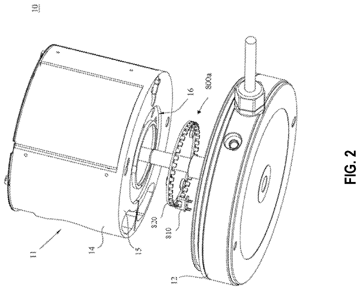
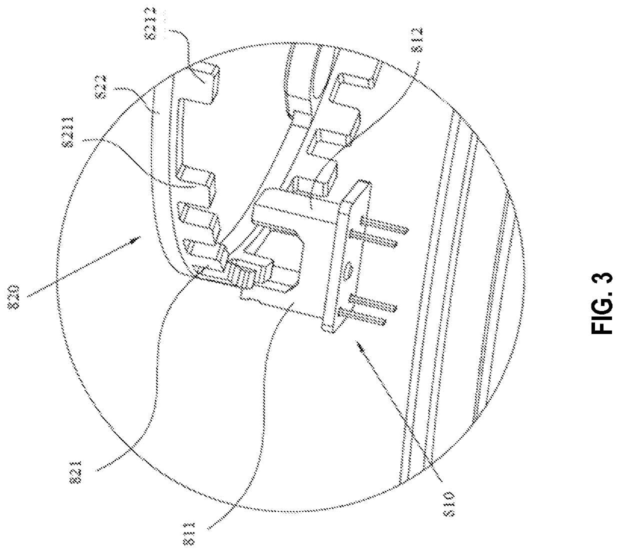
The present patent application provides a bearing mounting structure for a LiDAR, which includes a rotating body with a driving body and a shaft body, and a baffle fixing structure for the LiDAR. The bearing mounting structure reduces the overall length dimension of the LiDAR and improves its structural stability. The baffle fixing structure isolates the emitted laser from the reflected laser and improves the isolation effect between the emitted laser and the receiving laser. The angular displacement measurement device includes a reflecting part and a light emitting part, and the assembly between the two parts may be completed through the assembly of the base and the rotating body, thereby improving the assembly efficiency. The patent also provides a method for measuring the angle of rotation of the reflecting part relative to the light emitting part by obtaining a quantity of the reflecting teeth swept by the measurement light.

Problems solved by technology

However, such a structure makes the LiDAR have a complex structure and high production costs.
Moreover, the transceiver device of the LiDAR is typically arranged inside the housing, which makes the assembly complicated and further and the disassembly inconvenient.

Method used


Image

  • Lidar
  • Lidar
  • Lidar

Examples


Embodiment Construction

[0039]The following description provides specific scenarios and requirements of the present application for the purpose of enabling those skilled in the art to make and use the contents of the present application. Various sectional modifications to the disclosed embodiments are obvious to those skilled in the art, and the general principles defined herein may be applied to other embodiments and applications without departing from the spirit and scope of the present disclosure. Therefore, the present disclosure is not limited to the embodiments shown, but is consistent with the broadest scope of the claims.

[0040]The terminology used herein is for the purpose of describing particular exemplary embodiments only and is not intended to be limiting. As used herein, the singular forms “a,”“an” and “the” may include their plural forms as well, unless the context clearly indicates otherwise. When used in this disclosure, the terms “comprises,”“comprising,”“includes” and / or “including” refer ...


PUM


Abstract

The present application provides a LiDAR. A baffle fixing structure of the LiDAR is set between an inner housing of the LiDAR and a second housing for fixing a baffle that isolates an emitting laser from a reflected device. An angular displacement measuring device of the LiDAR includes a reflecting part and a light emitting part, wherein the reflecting part includes a plurality of reflecting teeth that extend downwardly and are spaced from each other, the light emitting part obtains a rotation angle of the reflecting part relative to the light emitting part by obtaining the number of the reflecting teeth passed by the measurement light. A rotating system in the LiDAR is arranged on one side of the laser transceiver system and is detachably connected to the laser transceiver system, so that modular production can be carried out, and the production efficiency is improved.

Description

CROSS-REFERENCE TO RELATED APPLICATION[0001]The present application is a continuation of International Application No. PCT / CN2020 / 117266, filed Sep. 24, 2020, which claims the benefit of priority to International Application No. PCT / CN2019 / 107846, filed Sep. 25, 2019, China Patent Application No. CN201910912316.0, filed Sep. 25, 2019, China Patent Application No. CN201910913604.8, filed Sep. 25, 2019, and International Application No. PCT / CN2019 / 115026, filed Nov. 1, 2019, the contents of which are incorporated herein by reference in their entireties.TECHNICAL FIELD[0002]The present application relates to the technical field of laser detection, and in particular to a LiDAR.BACKGROUND[0003]Light detection and ranging (LiDAR) is a radar system that emits a laser beam to detect the position, speed and other characteristics of an object, its working principle is that an transmitting system first emits an emitted laser to the detection area, and then a receiving system receives the refle...

Claims


Application Information

Patent Timeline
Patent Type & Authority Applications(United States)
IPC IPC(8): G01S7/481G01S7/48
CPCG01S7/4813G01S7/4804G01S7/4817
Inventor YE, GAOSHANDENG, LEI
Owner SUTENG INNOVATION TECH CO LTD
Learn More